Make: Electronics (41 page)
Authors: Charles Platt

Tools
Four most common perfboarding errors
1. Too much solder
Before you know it, solder creeps across the board, touches the next copper trace, and sticks to it, as depicted in Figure 3-101. When this happens, you have to wait for it to cool, and then cut it with a utility knife. You can also try to remove it with a rubber bulb and solder wick, but some of it will tend to remain.
Even a microscopic trace of solder is enough to create a short circuit. Check the wiring under a magnifying glass while turning the perfboard so that the light strikes it from different angles (or use your solder wick to suck it away).

Figure 3-101.
If too much solder is used, it makes a mess and can create an unwanted connection with another conductor.
2. Not enough solder
If the joint is thin, the wire can break free from the solder as it cools. Even a microscopic crack is sufficient to stop the circuit from working. In extreme cases, the solder sticks to the wire, and sticks to the copper trace around the wire, yet doesn’t make a solid bridge connecting the two, leaving the wire encircled by solder yet untouched by it, as shown in Figure 3-102. You may find this undetectable unless you observe it with magnification.
You can add more solder to any joint that may have insufficient solder, but be sure to reheat the joint thoroughly.

Figure 3-102.
Too little solder (or insufficient heat) can allow a soldered wire to remain separate from the soldered copper on the perforated board. Even a hair-thin gap is sufficient to prevent an electrical connection.
3. Components incorrectly placed
It’s very easy to put a component one hole away from the position where it should be. It’s also easy to forget to make a connection.
I suggest that you print a copy of the schematic, and each time you make a connection on the perforated board, you eliminate that wire on your hardcopy, using a highlighter.
4. Debris
When you’re trimming wires, the little fragments that you cut don’t disappear. They start to clutter your work area, and one of them can easily get trapped under your perforated board, creating an electrical connection where you don’t want it.
This is another reason for working with something soft, such as polyurethane foam, under your project. It tends to absorb or hold little pieces of debris, reducing the risk of you picking them up in your wiring.
Clean the underside of your board with an old (dry) toothbrush before you apply power to it, and keep your work area as neat as possible. The more meticulous you are, the fewer problems you’ll have later.
Once again, be sure to check every joint with a magnifying glass.
Transferring components from the breadboard to the perforated board should be fairly simple, as long as you don’t try to move too many at once. Follow the suggestions described in previous section “Essentials: Perfboard procedure,” and pause frequently to check your connections. Impatience is almost always the cause of errors in this kind of work.
Figure 3-103 shows the noisemaker section of the circuit on perfboard, with the components positioned to minimize wasted space. Figure 3-104 shows the perfboard with the relay and its associated components added. The two black wires will go to the loudspeaker, the black-and-red pair of wires will bring power to the board, and the green wires will go to the magnetic sensor switches. Each wire penetrates the board, and its stripped end is soldered to the copper beneath.

Figure 3-103.
The noisemaker circuit has been transplanted from breadboard to perforated board, with no additions or changes.
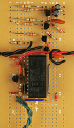
Figure 3-104.
The relay-transistor control circuit has been added. Wires to external devices have been stripped and poked into the perforated board, where they are soldered in place. The green wires connect with the sensor network, the black wires go to the loudspeaker, and the red-and-black wires supply power.
Test it now, in the same way that you tested the same circuit on the breadboard. If it doesn’t work, check the following section, “Essentials: Real-world fault tracing.” If it does work, you’re ready to trim the board and mount it in a project box.
Essentials
Real-world fault tracing
Here’s a real-life description of the procedure for tracing a fault.
After I assembled the perfboard version of the combined noisemaker and relay circuit, I checked my work, applied power—and although the relay clicked, no sound came out of the loudspeaker. Of course, everything had worked fine on the breadboard.
First I looked at component placement, because this is the easiest thing to verify. I found no errors. Then I flexed the board gently while applying power—and the loudspeaker made a brief “beep.” Any time this happens, you can be virtually certain that a solder joint has a tiny crack in it.
The next step was to anchor the black lead of my meter to the negative side of the power supply, and then switch on the power and go through the circuit point by point, from top to bottom, checking the voltage at each point with the red lead of the meter. In a simple circuit like this, every part should show at least some voltage.
But when I got to the second 2N2222 transistor, which powers the loudspeaker, its output was completely dead. Either I had melted the transistor while soldering it (unlikely), or there was a bad joint. I checked the perfboard beneath the transistor with the magnifying glass, and found that solder had flowed around one of the leads of the transistor without actually sticking to it. The gap must have been less than one-thousandth of an inch, but still, that was enough. Probably, the problem had been caused by dirt or grease.
This is the kind of patient inquiry you need to follow when a circuit doesn’t work. Check whether your components are placed correctly, check your power supply, check the power on the board, check the voltage at each stage, and if you are persistent, you’ll find the fault.
Switches and Inputs for the Alarm
Now you need to make the system easy to use. The block diagram in Figure 3-105 shows one additional box near the top of the sequence: User Controls. These will consist of switches, LEDs, and connections to the outside world. To plan this part of the job, first I have to summarize the way in which our alarm system works at this point in its evolution.

Figure 3-105.
The final block diagram for this phase of the project shows where user controls fit in the series of functions.
A full-featured home alarm system normally has two modes: in-home and away-from-home:
- Using the in-home mode, you switch on the alarm while you are at home so that it will alert you if an intruder opens a door or window.
- Using the away-from-home mode, typically you enter a code number, after which you have 30 seconds to leave and close the door behind you. When you return, you trigger the alarm by opening the door, but now you have 30 seconds to go to the control panel and enter your code number again to stop the alarm from sounding.
So far, the alarm system that you’ve been building has only an in-home mode. Still, many people find this function useful and reassuring. Later in the book I’ll suggest a way in which you can modify it to incorporate an away-from-home mode, but for now, making it practical for in-home use is enough of a challenge.
Consider how it should be used on an everyday basis. It should have an on/off switch, naturally. When it’s on, any of the magnetic sensor switches should trigger the alarm. But what if you switch it on without realizing that you’ve left a window open? At that time it won’t be appropriate for the alarm to sound. What you really need is a circuit-test feature, to tell you if all the doors and windows are closed. Then you can switch on the alarm.
I think a pushbutton would be useful to test the alarm circuit. When you press it, a green LED should light up to indicate that the circuit is good. After you see the green light, you let go of the pushbutton and turn on the power switch, which illuminates a red LED, to remind you that the alarm is now armed and ready.
One additional feature would be useful: an alarm noisemaker test feature, so that you can be sure that the system is capable of sounding its alert when required to do so.
The circuit shown in Figure 3-106 incorporates all of these features. S1 is a SPDT switch; S2 is a DPDT momentary pushbutton of ON-(ON) type. I spliced S2 into the circuit by first cutting the two green wires that connect the sensor switches with the rest of the relay circuit. I then attached one pair of those wires to one side of S2 and the other pair to the other side, as shown in the figure. The schematic shows it in its “relaxed” mode, when the button is not being pressed.