Make: Electronics (35 page)
Authors: Charles Platt

7.
When the joint has cooled, slide the heat-shrink tubing over it, and apply the heat gun. Now repeat the process with the other conductor. Finally, slide the larger piece of tubing over the joint. You did remember to put the large tubing onto the wire at the beginning, didn’t you?
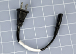
Figure 3-65.
Completion of the shortened power cord for a laptop power supply.
Figures 3-59 through 3-65 show the steps all the way through to the end.
If you have completed the soldering exercises so far, you now have sufficient basic skills to solder your first electronic circuit. But first, I want you to verify the vulnerability of components to heat.
Experiment 13: Broil an LED
In
Chapter 1
, you saw how an LED can be damaged if too much current flows through it. The electricity caused heat, which melted the LED. Unsurprisingly, you can just as easily melt it by applying too much heat to one of its leads with a soldering iron. The question is: how much heat is too much? Let’s find out.
You will need:
- 30-watt or 40-watt soldering iron
- 15-watt pencil-type soldering iron
- A couple of LEDs (that are expendable)
- 680Ω resistor
- Wire cutters and sharp-nosed pliers
- “Helping hand” gadget to hold your work
I don’t want you to use alligator clips to join the LED to a power supply, because the alligator clip will divert and absorb some of the heat from your soldering iron. Instead, please use some sharp-nosed pliers to bend each of the leads from an LED into little hooks, and do the same thing with the wires on a 680Ω load resistor. Finally bend the new wires on your AC adapter so that they, too, are tiny hooks. Now you can put the hooks together like links in a chain, as shown in Figure 3-66.
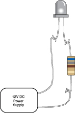
Figure 3-66.
By literally hooking together the leads from a resistor and a white-light LED, we minimize pathways for heat to escape during the subsequent test.
Grip the plastic body of the LED in your helping hand. Plastic is not a good thermal conductor, so the helping hand shouldn’t siphon too much heat away from our target. The resistor can dangle from one of the leads on the LED, and the wire from the AC adapter can hang from that, a little farther down. Gravity should be sufficient to make this work. Set your AC adapter to deliver 12 volts as before, plug it in, and your LED should be shining brightly. I used a white LED in this experiment, because it’s easier to photograph.
Make sure your two soldering irons are really hot. They should have been plugged in for at least five minutes. Now take the pencil-style iron and hold its tip firmly against one of the leads on your glowing LED, while you check the time with a watch. Figure 3-67 shows the setup.
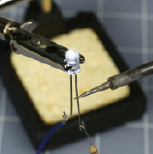
Figure 3-67.
Applying heat with a 15-watt soldering iron. A typical LED should withstand this treatment for two or three minutes, but if you substitute a 30-watt soldering iron, the LED is likely to burn out in under 15 seconds.
I’m betting that you can sustain this contact for a full three minutes without burning out the LED. This is why you use a 15-watt soldering iron for delicate electronics work—it doesn’t endanger the components.
Allow your LED wire to cool, and then apply your more powerful soldering iron to the same piece of wire as before. Again, make sure it is completely hot, and I think you’ll find that the LED will go dark after as little as 10 seconds (note, some LEDs can survive higher temperatures than others). This is why you
don’t
use a 30-watt soldering iron for delicate electronics work.
The large iron doesn’t necessarily reach a higher temperature than the small one. It just has a larger heat capacity. In other words, a greater quantity of heat can flow out of it, at a faster rate.
Throw away your burned-out LED. Substitute a new one, connected as before, but add a full-size copper alligator clip to one of the leads up near the body of the LED, as shown in Figure 3-68. Press the tip of your 30-watt or 40-watt soldering iron against the lead just
below
the alligator clip. This time, you should be able to hold the powerful soldering iron in place for a full two minutes without burning out the LED.
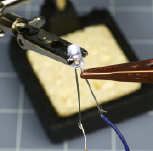
Figure 3-68.
When a copper alligator clip is used as a heat sink, you should be able to apply a 30-watt soldering iron (below the clip) without damaging the LED.
Imagine the heat flowing out through the tip of your soldering iron, into the wire that leads to the LED—except that the heat meets the alligator clip along the way, as shown in Figure 3-69. The clip is like an empty vessel waiting to be filled. It offers much less resistance to heat than the remainder of the wire leading to the LED, so the heat prefers to flow into the copper clip, leaving the LED unharmed. At the end of your experiment, if you touch the clip, you’ll find that it’s hot, while the LED remains relatively cooler.
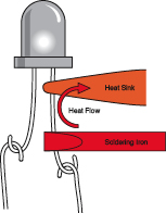
Figure 3-69.
The heat sink intercepts the heat, sucks it up, and protects the LED from damage.
The alligator clip is known as a heat sink, and it should be made of copper, because copper is one of the best conductors of heat.
Because the 15-watt soldering iron failed to harm the LED, you may conclude that the 15-watt iron is completely safe, eliminating all need for a heat sink. Well, this may be true. The problem is, you don’t really know whether some semiconductors may be more heat-sensitive than LEDs. Because the consequences of burning out a component are so exasperating, I suggest you should play it safe and use a heat sink in these circumstances:
- If you apply 15-watt iron extremely close to a semiconductor for 20 seconds or more.
- If you apply a 30-watt iron near resistors or capacitors for 10 seconds or more. (Never use it near semiconductors.)
- If you apply a 30-watt iron near anything meltable for 20 seconds or more. Meltable items include insulation on wires, plastic connectors, and plastic components inside switches.
Rules for Heat Sinking
1.
Full-size copper alligator clips do work better.
2.
Clamp the alligator clip as close as possible to the component and as far as possible from the joint. (You don’t want to suck too much heat away from the joint.)
3.
Make sure there is a metal-to-metal connection between the alligator clip and the wire to promote good heat transfer.
Fundamentals
All about perforated board
For the remainder of this book, you’ll be using perforated board whenever you want to create permanent, soldered circuits. There are three ways to do this:
1.
Point-to-point wiring. You use perforated board that has no connections behind the holes. Either the board has no copper traces on it at all, as in Figure 3-70, or you will find a little circular copper circle around each hole, as in Figure 3-71. These circles are not connected with each other and are used only to stabilize the components that you assemble.
Point-to-point wiring allows you to place the components in a convenient, compact layout that can be very similar to a schematic. Under the board you bend the wires to link the components, and solder them together, adding extra lengths of wire if necessary. The advantage of this system is that it can be extremely compact. The disadvantage is that the layout can be confusing, leading to errors.
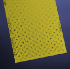
Figure 3-70
.
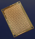
Figure 3-71.
Either this type of perforated board or the type in Figure 3-70 can be used for point-to-point wiring in
Experiment 14
.
2.
Breadboard-style wiring. Use perforated board that is printed with copper traces in exactly the same pattern as the conductors inside a breadboard. Once your circuit works on the breadboard, you move the components over to the perfboard one by one, maintaining their exact same positions relative to each other. You solder the “legs” of the components to the copper traces, which complete the circuit. Then you trim off the surplus wire. The advantage of this procedure is that it’s quick, requires very little planning, and minimizes the possibility for errors. The disadvantage is that it tends to waste space. A cheap example is shown in Figure 3-72.
3.
You can etch your own circuit board with customized copper traces that link your components in a point-to-point layout. This is the most professional way to complete a project, but it requires more time, trouble, and equipment than is practical in this book.
Point-to-point wiring is like working with alligator clips, on a much smaller scale. The first soldered project will use this procedure.
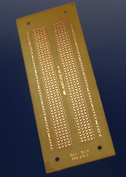
Figure 3-72.
Perforated board etched with copper in variants of a breadboard layout. This example is appropriate for
Experiment 15
.