Make: Electronics (58 page)
Authors: Charles Platt

The Schematic
This time I’d like you to study the schematic before building anything. Let’s start with the simplified version, shown in Figure 4-83.
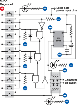
Figure 4-83.
A simplified schematic showing the basic structure of the combination lock circuit.
I want this to be a battery-powered circuit, so that you don’t have to run a separate power supply to it or (worse) try to tap into your computer’s 5-volt bus. Battery power means that the circuit has to be “off” most of the time, to prevent the battery from running down. Because the keypad has two spare buttons (the asterisk and the pound sign), I’m going to use the asterisk as the “power on” button. When you press it, the LED at the top of the schematic lights up to confirm that everything’s working, and the button sends power to the two logic chips and the 555 timer. You have to hold down the asterisk button while you punch in a three-digit code to unlock the computer.
Arbitrarily, I’ve chosen 1-4-7 as the three-digit code. Let’s track what happens when you enter this sequence. (Naturally, if you build the circuit, you can wire it to choose any three digits you prefer.)
Pressing the 1 button sends positive power to one logical input of the first AND gate. The other logical input of this gate is also positive, because an inverter is supplying it, and the input of the inverter is being held negative by a pull-down resistor. When an inverter has a negative input, it gives a positive output, so pressing the 1 button activates the AND gate, and makes its output positive. The AND gate locks itself on, as its output cycles back to its switched input via a diode. So the gate output remains high even after you let go of the 1 button.
The output from the first AND gate also supplies one logical input of the second AND gate. When you press the 4 button, you send positive voltage to the other logical input of this AND gate, so its output goes high, and it locks itself on, just as the first gate did.
The second AND gate feeds the third AND gate, so when you press the 7 button, the third AND gate changes its output from low to high. This passes through an inverter, so the output from the inverter goes from high to low. This in turn goes to the trigger of a 555 timer wired in monostable mode.
When the trigger of a 555 timer goes from high to low, the timer emits a positive pulse through its output, pin 3. This runs down to the upper coil of the latching relay, and also flashes an LED to confirm that the code has been accepted and the relay has been activated.
Two of the contacts in the relay are wired into the power-up button of your computer. A little later in this description I’ll explain why this should be safe with any modern computer.
Because we’re using a latching relay, it flips into its “on” state and remains there, even when the power pulse from the timer ends. So now you can let go of the asterisk button to disconnect the battery power to your combination lock, and press the power-up button that switches on your computer.
At the end of your work session, you shut down your computer as usual, then press the pound button on your keypad, which flips the relay into its other position, reactivating the combination lock.
Incorrect Inputs
What happens if you enter the wrong code? If you press any button other than 1, 4, or 7, it sends positive voltage to the inverter near the top of the schematic. The positive voltage overwhelms the negative voltage being applied to the inverter through a pull-down resistor, and causes the inverter to output a negative voltage, which it applies to one of the logical inputs of the first AND gate. If the AND gate was locked on, the negative input will switch it off. If it was supplying the second AND gate, it’ll switch that one off too.
Thus, any error when entering the first, second, or third digit of the secret code will reset the AND gates, forcing you to begin the sequence all over again.
What if you enter 1, 4, and 7 out of their correct sequence? The circuit won’t respond. The third AND gate needs a high input supplied by the second AND gate, and the second AND gate needs a high input supplied by the first AND gate. So you have to activate the AND gates in the correct sequence.
Questions
Why did I use a 555 timer to deliver the pulse to the relay? Because the logical output from an AND gate cannot deliver sufficient power. I could have passed it through a transistor, but I liked the idea of a pulse of a fixed length to flip the relay and illuminate an LED for about 1 second, regardless of how briefly the user presses the 7 button.
Why do I need three LEDs? Because when you’re punching buttons to unlock your computer, you need to know what’s going on. The Power On LED reassures you that your battery isn’t dead. The Relay Active LED tells you that the system is now unlocked, in case you are unable to hear the relay click. The System Relocked LED reassures you that you have secured your computer.
Because all the LEDs are driven either directly from the 5-volt supply or from the output of the 555 timer, they don’t have to be low-current LEDs and can be used with 330Ω series resistors, so they’ll be nice and bright.
How do you connect the keypad with the circuit? That’s where your ribbon cable comes in. You carefully strip insulation from each of the conductors, and solder them to the contact strip or edge connector on your keypad. Push the conductors on the other end of the cable into your breadboard (when you’re test-building the circuit) or solder them into perforated board (when you’re building it permanently). Find a convenient spot inside your computer case where you can attach the perforated board, with double-sided adhesive or small bolts or whatever is convenient. Include a 9-volt battery carrier, and don’t forget your power regulator to step the voltage down to 5 volts.
Breadboarding
No doubt you have realized by now that breadboards are very convenient as a quick way to push in some components and create connections, but the layout of their conductors forces you to put components in unintuitive configurations. Still, if you carefully compare the breadboard schematic in Figure 4-83 with the simplified schematic in Figure 4-84, you’ll find that the connections are the same.
To help it make sense, I’ve shown the logic gates that exist inside the chips. I’ve also colored the power supply wires, as before, to reduce the risk of confusion. The positive side of the supply goes only to the common terminal on your keypad, and you have to press the asterisk key to send the power back down the ribbon cable, to supply the chips.
If you build the circuit and you can’t understand why everything’s dead, it’s most likely because you forgot to hold down the asterisk button.
Note that the “wrong” numbers on the keypad are all shorted together. This will create some inconvenience if you want to change the combination in the future. I’ll suggest a different option in the “enhancements” section that follows. For now, ideally, you should run a wire from every contact on your keypad, down to your circuit on its breadboard, and short the “wrong” keypad numbers together with jumper wires on the breadboard.
Also note that if you use a meter to test the inputs to the AND gates, and you touch your finger against the meter probe while doing so, this can be sufficient to trigger the sensitive CMOS inputs and give a false positive.
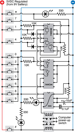
Figure 4-84.
The combination lock schematic redrawn to show how the components can be laid out on a breadboard.
One Little Detail: The Computer Interface
Old computers used to have a big switch at the back, attached to the heavy metal box inside the computer, that transformed house current to regulated voltages that the computer needs. Most modern computers are not designed this way; you leave the computer plugged in, and you touch a little button on the box (if it’s a Windows machine) or the keyboard (if it’s a Mac), which sends a low-voltage pulse to the motherboard.
This is ideal from our point of view, because we don’t have to mess with high voltages. Don’t even think of opening that metal box with the fan mounted in it, containing the computer power supply. Just look for the wire (usually containing two conductors, on a Windows machine) that runs from the “power up” button to the motherboard.
To check that you found the right one,
make sure that your computer is unplugged
, ground yourself (because computers contain CMOS chips that are sensitive to static electricity) and very carefully snip just one of the two conductors in the wire. Now plug in your computer and try to use the “power up” button. If nothing happens, you’ve probably cut the right wire. Even if you cut the wrong wire, it still prevented your computer from booting, which is what you want, so you can use it anyway. Remember, we are not going to introduce any voltage to this wire. We’re just going to use the relay as a switch to reconnect the conductor that you cut. You should have no problem if you maintain a cool and calm demeanor, and look for that single wire that starts everything. Check online for the maintenance manual for your computer if you’re really concerned about making an error.
After you find the wire and cut just one of its conductors, unplug your computer again, and keep it unplugged during the next steps.
Find where the wire attaches to the motherboard. Usually there’s a small unpluggable connector. First, mark it so that you know how to plug it back in the right way around, and then disconnect it while you follow the next couple of steps.
Strip insulation from the two ends of the wire that you cut, and solder an additional piece of two-conductor wire, as shown in Figure 4-85, with heat-shrink tube to protect the solder joints. (This is very important!)
Run your new piece of wire to the latching relay, making sure you attach it to the pair of contacts which close, inside the relay, when it is energized by the unlocking operation. You don’t want to make the mistake of unlocking your computer when you think you’re locking it, and vice versa.
Reconnect the connector that you disconnected from your motherboard, plug in your computer, and try to power it up. If nothing happens, this is probably good! Now enter the secret combination on your keypad (while holding down the asterisk button to provide battery power) and listen for the click as the relay latches. Now try the “power up” button again, and everything should work.
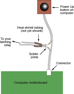
Figure 4-85.
The combination lock project can be interfaced with a typical desktop computer by cutting one conductor in the wire from the “power up” pushbutton, soldering an extension, and covering the joints with heat-shrink tube.
Enhancements
At the end of any project, there’s always more you can do.
To make this setup more secure, you could remove the usual screws that secure the case of the computer, and replace them with tamper-proof screws. Check any online source for “tamper-proof screws,” such as
http://www.mcmaster.com
. Naturally, you will also need the special tool that fits the screws, so that you can install them (or remove them, if your security system malfunctions for any reason).