125 Physics Projects for the Evil Genius (51 page)
Read 125 Physics Projects for the Evil Genius Online
Authors: Jerry Silver

Figure 86-2
Percentage of light blocked by polarizing filters
.
A light meter is a good way to quantify the amount of light passing through a filter.
Figure 86-2
provides an approximate visual reference to evaluate the amount of light transmission through a set of polarizing filters.
Reflected light can be polarized. This can be determined by observing the effect of a single polarized filter on reflected light.
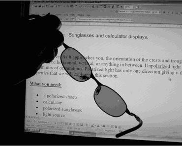
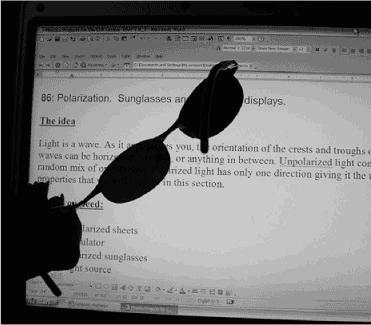
The light from a LCD, such as a laptop screen, is also polarized. This can be seen by rotating a polarized filter, such as polarized sunglasses, in front of an LCD screen, as shown in
Figure 86-3
and
Figure 86-4
.
Light is an electromagnetic wave that propagates along a line. If we can imagine looking down that line, we would see the waves from most light sources moving up and down in any direction. For unpolarized light, the wave oscillations are randomly distributed over 360 degrees. A polarized filter selects only one of the polarization planes. Reflection polarizes light by favoring light in the plane of the reflecting surface.

Figure 86-3
Polarized filter (sunglasses) oriented to pass polarized light from laptop
.
We saw how the more we rotated the polarized sheets, the less light they transmitted. Here, we find the physical model for that effect.
- Start with the two polarized sheets oriented (with taped sides aligned) to allow the maximum light to be transmitted.
- Find a way to measure or estimate the amount of light transmitted. Depending on your resources, this can include:
– Estimating the transmission visually by using a chart ranging from white 100 percent transmission to black 0 percent transmission.
Figure 86-5
may be a rough guide.
– Comparing the transmission using a set of calibrated neutral-density filters (that may be available in some labs). These transmit a specific amount of light without changing the color, so they might serve as a good visual comparison.

Figure 86-4
Polarized filter (sunglasses) oriented to block polarized light from laptop
.
– Using a light meter to measure the light transmitted. The percent would be the ratio of the light transmitted at a particular misorientation angle divided by the amount of light transmitted through the polarized filters when they are aligned. This works best if the room is darkened and the light from the source is isolated from the meter. One way to do this is to put the light in a box and cut a square hole smaller than the filters. The light meter can be purchased from a science supply company or made from a solar cell with solder wire leads connected to an ammeter (as described in
Project 81
).
3. Measure or estimate the amount of light transmission as a function of misalignment angle of the polarized sheets. Use the following data table to organize your data.

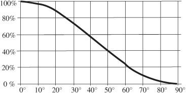
The expected results are described by this is called Malus’s law.
The greater the misorientation, the less light is transmitted. The drop-off, however, is not linear but is, instead, given by:
Fraction of light transmitted, I/I
o
= cos
2
θ
The expected results are given in
Figure 86-5
.
Previously in this section, you saw that light reflecting from a piece of glass can be polarized if the angle (with respect to the normal) is great enough. That angle is called
Brewster’s angle
.
- Place a sheet of glass flat on a table.
- Using a protractor as a guide, view the reflected light at various angles. Use a straight edge positioned near the protractor as a visual guide to establish the reflected angle.
- Determine the maximum angle with respect to the perpendicular that results in reflected polarized light. That is Brewster’s angle.
- Compare your result with the expected value of Brewster’s angle given by:
n = tanθ
p
where
n
is the index of refraction for the glass and θ
p
is the angle where the reflected light is completely polarized.

Figure 86-5
Malus’s law
.
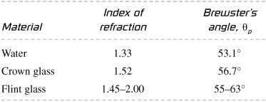
Some typical values are given in the following table:

- Place several objects (coins, rocks) in a pan of water.
- Cover the objects with several inches of water.
- Establish a light source at an angle.
- Find a position to view the surface of the water, so you see the reflected light shimmering at the surface of the water obscuring the objects below.
- View the light using the polarizing filter. View at angles both greater and lesser than Brewster’s angle through the polarizing filter. Under what conditions are you able to see the underwater objects?
Typical light sources, such as light bulbs or the sun, produce unpolarized light that has electromagnetic waves oriented randomly. Light can be polarized by filters or certain reflecting surfaces that select a specific orientation of the light waves.
What is the wire of a fiber-optic network? Total internal reflection using a laser and a tank of water
.
Much of the digital communication that circulates around the world on the Internet consists of light traveling thousands of miles through glass threads thinner than human hair. Total internal reflection is the physical process that keeps these information pulses confined within these tiny optical fibers. In this experiment, you can set up various ways to explore how transparent materials guide light by total internal reflection.
- laser pointer
- fish tank (preferably with a glass bottom)
- tablespoon of milk
- dark room
- sink
- one 2-L clear plastic soda bottle
- Fill the tank with water.
- Turn off the room lights.
- Direct the laser from the side of the tank under the level of the water toward the surface.
- Add enough milk to the water in the tank so the path of the laser is visible as it passes through the water.
- If the fish tank has a glass bottom, direct the laser through the fish tank from the bottom at various angles.
- Determine the maximum angle that will allow the light to emerge from the tank.
- Punch a small hole about 1 mm in diameter in the side of the plastic gallon container.
- Fill the container with water.
- Darken the room.
- As the water flows from the hole into the sink, shine the laser from the other side of the bottle, but aim it at the hole.
- Observe how the light passes through the bottle and is guided through the water stream pouring out of the bottle. This is because the light is trapped in the water stream by total internal reflection. With an index of refraction of 1.33 for water, any light incident on the surface at an angle greater than 48.7 degrees will be totally reflected. This is much lower than the angles the light makes with the water stream.
An acrylic (or other transparent material) makes a good demonstration of light trapped in a medium by total internal reflection. Send the beam through one of the flat ends. Regardless of what angle you direct the beam, the light will not refract out through the sides of the cylinder.
Optical fibers show very convincingly how light travels through a thin transparent material. Optical fibers are available from scientific supply companies and novelty lighting stores.
Light passing through the water and striking the surface passes through to the air if the angle is above the critical angle for water.
Figure 87-1
shows light passing through plastic at an angle less than the critical angle. Notice that most of the light is refracted (or goes through) the lens with a smaller part of the light being reflected at the flat surface.
However, once the incident angle coming from the plastic back into the air is greater than the critical angle for those materials, the light experiences total internal reflection, as shown in
Figure 87-2
. Here, light is effectively trapped inside the plastic and cannot emerge back into the air.