125 Physics Projects for the Evil Genius (50 page)
Read 125 Physics Projects for the Evil Genius Online
Authors: Jerry Silver

Suppose you find the average of the hot-spot distance is 6 cm.
The wavelength of the microwave resonant in the microwave oven is 12 cm.
In meters, this is 12 cm × 0.01 m/cm = 0.12 m.
The speed of light is then, c = 0.12m × 2,450,000,000Hz = 2.94 × 10
8
m/s.
This is reasonably close to the accepted value, which is just under 3 × 10
8
m/s (300,000,000 m/s). Remember, microwaves may vary in how they create standing waves and an error factor is associated with heat distribution on the heat surface. For this reason, this measurement can be only expected to give ballpark, not precisely accurate, values.
A microwave oven produces a resonant wave in the oven chamber similar to that of a vibrating guitar string. The hot spots are like the nodes or the points where the ends of the string are held. A complete wave is a cycle up and down, so only a half wave fits between the two nodes in both cases. From knowing the frequency of the microwaves and measuring its wavelength, we can find the speed of light.
A more sophisticated, but more precise way to measure the speed of light is to detect the interference between light waves separated by a measurable distance. Equipment to do this is available from scientific supply vendors, such as PASCO.
The speed of a wave, such as light, can be determined from its wavelength and frequency. The wavelength of a microwave oven can be found by the distance between the nodes of a resonant standing wave.
Refraction. How fast does light travel in air or water
?
Light travels at its top speed in a vacuum and at (nearly) its top speed in air. When light moves through other transparent materials, it slows down. If it goes from one material to another at an angle, the light will bend. The more it slows down, the more it bends. In this project you will compare how much light bends in various materials. This bending is called
refraction
and it gives us a way to determine how fast light travels in a transparent material.
- square or rectangular piece of glass about ¼ inch thick and a few inches in length and width (at least two opposing sides must be clear)
- laser pointer
- semicircular plastic container filled with water
- protractor
1. Place the piece of glass on the paper.
2. Trace the shape of the glass.
3. Darken the room.
4. Put a dot on one side of the glass to provide a target for the laser.
5. Draw a line perpendicular to the edge of the glass at that point. Extend the line, so it extends under the glass, as well as going into it.
6. Place the laser, so its beam forms an angle with respect to the perpendicular line you just drew. Mark the position of the laser.
7. Darken the room.
8. Shine the laser and direct its beam toward the target dot. Angle the beam vertically, so you can see its path both before entering and after exiting the glass. (It is OK if you don’t see the entry and exit beams at the same time.)
9. Place a dot where you see the laser beam exit from the glass and one or two dots along its path.
10. Connect the dot where the light strikes the glass with the point where the light ray emerges from the glass back into the air.
11. Measure the angles that:
– the incoming ray made with the perpendicular line (θ
i
).
– the ray going through the glass made with the edge where the light entered the glass (θ
r
).
Expected Results12. Try this with other transparent materials such as water (in a plastic case).
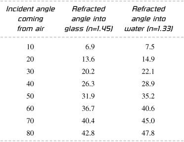
Going from air into water, the light path is bent to give a smaller angle with respect to the perpendicular line. Specific results are given in the following chart:

The relationship between the incident and refracted angles is given by Snell’s law, which states:
n
i
sin(θ
i
) = n
r
sin(θ
r
)
where n
i
is the index of refraction where the ray is incident and n
r
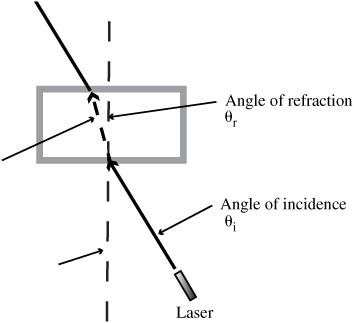
is the index of refraction where the ray is refracted. Both are measures of the speed of light in the various materials, The index of refraction for any material is given by n = c/v. The physical arrangement for this is shown in
Figure 85-1
.
The index of refraction for air, which is 1.0, indicates that light is traveling at its maximum speed.
Because light slows down in glass,
n
for glass is 1.45.

Figure 85-1
Find the index of refraction for the glass or water using the equation:
n
i
sin(θ
i
) = n
r
sin(θ
r
)
using n
i
for air = 1.0 and θ
I
and θ
r
as defined in the previous step to find the index of refraction in the material of interest. The index of refraction is given by:
n = c/v
The index of refraction is a measure of the speed of light in a particular material, v, compared to the speed of light in a vacuum which is given by c = 3.0 × 10
8
m/s.
The speed of light in a particular medium is given by v = c/nr.
Light travels at a slower velocity when it goes through materials other than vacuum or air. When light hits a boundary going from a material where the light is faster to one where it is slower, the light bends toward the perpendicular line.
Polarization. Sunglasses and calculator displays
.
The orientation of the crests and troughs of light waves can be horizontal, vertical, or anything in between.
Unpolarized light
consists of a random mix of orientations.
Polarized light
has only one direction. This gives it the unique properties used in liquid crystal displays found in many television screens and computer monitors. Sunglasses reduce glare by allowing only selected orientations of polarized light through. This experiment explores how to identify whether light is polarized and how the transmission of polarized light can be controlled.
- 2 polarized sheets
- calculator or other LCD display, such as a laptop computer
- polarized sunglasses
- light source
- shallow tray
- water
- few rocks
- sheet of glass
- optional: protractor, light sensor
- Take one of the polarized sheets. Hold it in front of a light source (a lamp or an open window) and rotate it. Turn the sheet a full 360 degrees, holding the sheet so it remains roughly perpendicular to your field of view.
- Try this with the other sheet.
- Now, with both sheets, hold them in front of the light, one in front of the other, and rotate only one of them. Observe what happens. Add in other combinations: rotate both in the same direction, rotate both, but in different directions. Describe the effect of the sheets. Is the light from your light source polarized?
- Using a nondestructive method, such as applying a small piece of tape, identify an edge on each, which when placed together, blocks the maximum amount of light.
- Note: This is good to do using an overhead projector or the light from an LCD projector.
- Place a small flat mirror face up on a table.
- Place a light source on one side of the mirror.
- View the reflected light through one of the polarized sheets as you rotate the sheet. Is that light polarized? View through a range of reflected angles from nearly perpendicular to a very glancing angle to the mirror.
- Place the two sheets, one on top of the other, but with taped edges aligned, so both sheets have the same polarization plane. What happens when you rotate the sheets, both with respect to the mirror and to each other?
- Repeat 1–4, using light reflected from a square of glass.
- Hold a polarized sheet in front of the LCD (liquid crystal display) of a laptop computer or digital calculator.
- Rotate the polarized sheet. What can you conclude about the LCD of the laptop?
- Take the two lenses from an old (no longer needed) pair of polarized sunglasses. Hold them—one in front of the other—and view a light source. Are the glasses polarized? You also can try this with two pairs of polarized sunglasses.
Light will pass through polarized sheets with little loss when the directions of polarization for both sheets line up. As the sheets are rotated, more and more of the light is blocked. With the direction of polarization of the two sheets at right angles, almost no light can pass through, as shown in
Figure 86-1
. This can be quantified in Malus’s law, which is addressed later in this section.

Figure 86-1
