125 Physics Projects for the Evil Genius (56 page)
Read 125 Physics Projects for the Evil Genius Online
Authors: Jerry Silver

The reverse—where electrical current flowing through certain materials results in one part of the circuit getting hot and the other part getting cold—is known as the
Peltier effect
. Unwanted heat is dissipated by electronic components. These components must be cooled to function correctly. Peltier coolers have no moving parts and have been used to cool high-speed computer microprocessors. They are also used instead of dry ice in cloud chambers. (See
Project 125
.)
- voltmeter (or multimeter configured as an voltmeter)
- ammeter (or multimeter configured as an ammeter)
- variable DC power supply
- jumpers with alligator clips
- 1000 ohm resistor
- 2 4-inch lengths of various types of (uninsulated) metal wire, including iron, copper, constantan, and aluminum
- heat source, such as a candle, Bunsen burner, or a soldering iron
- ice cubes
- optional: 2 thermocouples to be used as temperature sensors
- Select two different wire materials. Take two pieces of the first material and one piece of the second material. Let’s say we start with two pieces of iron and one piece of copper.
- Attach each end of the copper wire to each of the two pieces of iron wire by twisting about a one-half inch length of the wire together.
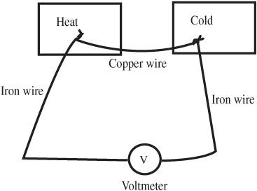
- Connect the two unattached ends of the iron wire to the positive and negative terminals of the voltmeter. See
Figure 95-1
. Set the voltmeter on the most sensitive setting. The 250 mV (0.250 V) range is a good place to start. - Measure the voltage at room temperature. (Momentarily disconnect one of the voltmeter connections to verify that the voltage you are reading is the result of the circuit you set up, rather than a small stray voltage reading.)
- Touch one junction (twisted wire connection) to the ice, leaving the second junction at room temperature. How does that affect the voltage reading?

Figure 95-1
Wiring arrangement for measuring the Seebeck effect
.
- Place the second junction in the heat source and see what happens. Be careful because the various metal wires conduct heat and can burn anything that comes in contact with it.
- Try this with as many material combinations as you can.
- Place a temperature sensor on each of the twisted metal junctions. Vary the junction temperatures. Plot the voltage as a function of the
difference between
the two junction temperatures.
- As before, connect each end of one piece of wire to a piece of a second type of metal wire.
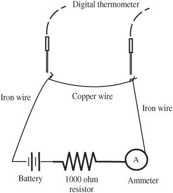
- Connect the components as a series circuit consisting of the wires, the ammeter, a 1000 ohm resistor, and an ammeter. This circuit is shown in
Figure 95-2
. - Adjust the DC power supply, so about 10mA (10 milliamps or 0.01 amps) is flowing through the circuit. (You can use a 9-volt battery instead of an adjustable DC power supply, which results in slightly less than this current with the 1000 ohm resistor.)
- Put water on each of the junctions. What happens? Reverse the direction of the current flow by exchanging the wire connected to the DC power supply. How does that affect what you find?

Figure 95-2
Apparatus for the Peltier effect
.
- Monitor the temperature of each of the junctions as you vary the current flowing through the circuit. Plot the temperatures of each junction and the difference versus the current.
In the Seebeck effect, a temperature difference at the two junctions results in a voltage generated through the circuit.
The Peltier effect results in temperature differences at the junctions when a current flows through the circuit.
A temperature difference between two dissimilar metals results in an electrical potential that drives a current through a circuit. The reverse effect causes a temperature difference when a current flows.
Commercial thermocouples that employ dissimilar metals are based on the Peltier effect and can be used to study this principle. Some temperature control devices that serve as a means of studying the Seebeck effect are available commercially.
The Seebeck effect and Peltier effect describe a set of interactions between the thermal properties and the electrical properties of matter.
Electricity and Magnetism
Static charges
.
According to Newton’s law of universal gravitation, any mass exerts a force on any other mass. Electric charges work in a very similar way. The farther away you get, the weaker the force. Because the electric force is so much stronger than the gravitational force, it is much easier to measure. This experiment explores the nature of the electrostatic force and establishes the basis for Coulomb’s law.
- 2 pith balls or conductively coated Styrofoam balls (conductively coated ping-pong balls are also an option)
- 2 pieces of string about 16 inches in length
- movable ring stand with a pendulum clamp (or other horizontal support)
- small
nonconductive
post on a stand (the post should be a few inches in length and consist of a thin wooden dowel or a short glass or plastic rod) - ruler
- rubber rod/wool pair (or equivalent) to apply a charge to the pith balls
- optional: light source to project the image of the pith balls onto a screen (an overhead project or LCD projector can serve this purpose)
- Attach one side of each of the two strings to the pith ball.
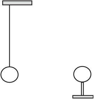
- Attach the other sides of the string to the pendulum clamp separated by a few inches, so the pith ball can swing in only one direction, as shown in
Figure 96-1
. - Attach the other pith ball to the nonconductive stand.
- The swinging pith ball should be positioned so it can only swing closer to and further from the stationary ball.
- Draw a reference mark on the bottom of the ring stand to indicate the rest position of the swinging pith ball without being subjected to any force other than gravity.
- Vigorously rub the wool against the rubber rod to charge it up. Touch each of the pith balls to apply the same charge to them. Touching the two balls together will make the charges nearly equal, but it is not necessary to do this.
- Start with a distance between the pith balls that allows the swinging ball to hang vertically.
- Slowly bring the swinging pith ball closer until the repulsion between the two pith balls causes the swinging pith ball to move away from the stationary ball.
- Measure how far the swinging pith ball moves
horizontally
. You may do this by observing from above and measuring the distance the ball has moved from the reference point. - Record the horizontal distance between the centers of each of the pith balls.
- Repeat this measurement a few times by moving the swinging pith ball in a little closer.
- The horizontal separation,
x
, between the unconstrained pith ball and its equilibrium position is a good indication of the force. (This can actually be worked out in terms of the force, but this is unnecessary to explore the key point of this experiment.) For small angles that the pith ball makes with the vertical, the electrostatic force is directly proportional to the separation from equilibrium. - The separation between the stationary ball and the equilibrium positions is designated as
d
, as shown in
Figure 96-2
. The total distance between the two pith balls is given by d + x. Make a graph of the separation from equilibrium,
x
, and the distance, d + x, between the balls.

Figure 96-1
Two uncharged balls in equilibrium position
.

Figure 96-2
Two charged balls show displacement from equilibrium position
.
The closer the two balls get, the greater the force.
This relationship is not linear.
The closer the balls get, the faster the increase in force between the balls.
Specifically, this is an inverse square relationship.
Overall, this experiment works best on a day with low humidity.
Coulomb’s law
states that the force (in newtons) between two charges, q
1
and q
2
(in Coulombs or C), separated by a distance,
d
(in meters), is given by:
