But How Do It Know? - the Basic Principles of Computers for Everyone (17 page)
Read But How Do It Know? - the Basic Principles of Computers for Everyone Online
Authors: J Clark Scott

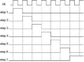
It has two inputs. One is called ‘clk,’ because this is where we connect a bit that is going on and off, such as our original clock bit. The other input is called ‘reset,’ which is used to return the stepper back to step one. For outputs, it has a number of bits, each of which will come on for one complete clock cycle, and then turn off, one after the other. The output labeled ‘Step 1’ turns on for one clock cycle, then ‘Step 2’ for the next clock cycle, etc. A stepper can be built to have as many steps as needed for any particular task you want to do. In the case of this computer that we are building, seven steps are sufficient. When the last step (7) turns on, it stays on, and the stepper doesn’t do anything else until the reset bit is turned on briefly, at which time the steps start over again beginning with ‘Step 1.’
Here is a graph of the input ‘clk’ bit, and the outputs of a seven-step stepper.

Here is how the stepper is built. It is done using some of the same memory bits that we used to make registers, but they are arranged very differently. We are not going to store anything in these bits, we are going to use them to create a series of steps.
The stepper consists of several memory bits connected in a string, with the output of one connected to the input of the next. Here is a diagram that shows most of the stepper:

First look at the series of ‘M’ memory bits just like the ones that we used earlier in the book. In this picture, there are twelve of them connected together, with the output of one connected to the input of the next, all the way down the line. The input to the first bit on the left is connected to a place where the electricity is always on, so when the set bit of that ‘M’ comes on, that ‘M’ will receive that on state, and pass it through to its output.
If you look at the set bits of these ‘M’s, you will see that the set bits of the even numbered ‘M’s are connected to clk, and the set bits of the odd numbered ‘M’s are connected to the same clock after it goes through a NOT gate. This new bit that is made by passing clk through a NOT gate can be called ‘not clk,’ and we can show both on this graph:

So what will happen with this bunch of gates? If you assume that all of the ‘M’s start in the off state, and then start ‘clk’ “ticking,” here is what it will do.
The first time ‘clk’ comes on, nothing will happen, because the set bit of the first ‘M’ is connected to ‘not clk,’ which is off when ‘clk’ is on. When ‘clk’ goes off, ‘not clk’ turns on, and the first ‘M’ will come on, but nothing will happen at the second ‘M’ because its ‘set’ bit is connected to ‘clk,’ which is now off. When ‘clk’ comes back on, the second ‘M’ will now come on. As the clock ticks, the ‘on’ that enters the first memory bit will step down the line, one bit for each time the clock goes on, and one bit for each time the clock goes off. Thus two bits come on for each clock cycle.
Now, turning to the full stepper diagram below, step 1 comes from a NOT gate connected to the output of the second ‘M.’ Since all ‘M’s start off, step 1 will be on until the second ‘M’ comes on, at which time step 1 will be over. For the remaining steps, each one will last from the time its left side ‘M’ turns on until the time its right side ‘M’ turns on. The AND gates for steps 2-6 have both inputs on when the left ‘M’ is on, and the right ‘M’ is off. If we connect the output of one ‘M’ and the NOT of the output of an ‘M’ two spaces farther on to an AND gate, its output will be on for one complete clock cycle. Each one comes on when its left input has come on, but its right input has not yet come on. This gives us a series of bits that each come on for one clock cycle and then turn off.
The only thing missing here is that the ‘M’ bits come on and stay on. Once they are all on, there is no more action despite the clock’s continued ticking. So we need a way to reset them all off so we can start over again. We have to have a way to turn off the input to the first ‘M,’ and then turn on all of the set bits at the same time. When that happens, the ‘off’ at the input to the first ‘M’ will travel through all of the ‘M’s as fast as it can go. We will add a new input called ‘reset,’ which will accomplish these things.

When we turn ‘reset’ on, it makes the input to the first ‘M’ bit a zero, and turns on all of the ‘sets’ at the same time so that the zero can travel down the line of ‘M’s very quickly. Reset is also ORed with step 1 so that step 1 turns on immediately. Now all of the bits are off, and we have started another sequence. Reset only needs to be turned on for a fraction of one clock cycle.
To recap, this is a stepper. It has two inputs: a clock and a reset. For outputs, it has a number of bits, each of which will come on for one clock cycle. We can actually make this as long as needed, but for the purposes of this book, a seven stage stepper will be sufficient. There will be only one stepper in our computer, we will represent it with this simplified diagram.

We have relocated the Reset bit to the right side of the diagram, and connected it to the last step (7,) so that the stepper will automatically reset itself. Step 7 will not be on for very long, however, because it shuts itself off as soon as the zero can get through the string of ‘M’s. This means that step 7 will not last long enough to be used for one of our data transfers over the bus. All of the things we want to accomplish will take place in steps 1 through 6.
Everything’s Under Control
With our clock, we have a drumbeat to make things go. It has a basic output, and two more that are designed to facilitate the movement of the contents of registers from one to another. With the stepper, we have a series of bits that come on one after another, each for one clock cycle.
Remember the diagram of the CPU we saw a few chapters back? It showed the bus, the ALU, six registers and even the other half of the computer (the RAM) all connected up pretty neatly. At least all of the bus connections were there. But all the registers, the RAM, the Bus 1 and the ALU are controlled by wires that come from that mysterious box labeled ‘Control Section’ that we know nothing about yet. Now it is time to look inside that box.

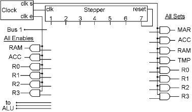
This drawing is the beginning of the control section of the computer. At the top are the clock and the stepper. Then all of the control bits from the registers and RAM have been brought here together in one place, with all of the ‘enable’ bits on the left, and all of the ‘set’ bits on the right. Then we have connected the output of an AND gate to each ‘enable’ and each ‘set’ bit. One input of each AND gate is connected to either ‘clk e’ for the ‘enables’ on the left, or ‘clk s’ for the ‘sets’ on the right. Thus, if we use the other input of those AND gates to select any of those registers, the ‘enable’ bit of all of the items on the left will never be turned on except during ‘clk e’ time. Similarly on the right, the ‘set’ bit of any of those registers will only be turned on during ‘clk s’ time.
This is sort of a switchboard. Everything we need to make the computer do something is right here in one place. All we need to do is connect some control bits to some steps in an intelligent manner, and something useful will happen.
Doing Something Useful, Revisited
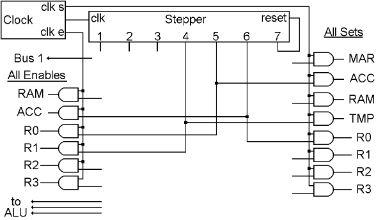
Now that we have the beginning of our control section, we can just add a few wires, and we will be able to do the simple addition we postulated earlier, that of adding R1 to R0.
