But How Do It Know? - the Basic Principles of Computers for Everyone (21 page)
Read But How Do It Know? - the Basic Principles of Computers for Everyone Online
Authors: J Clark Scott

Fortunately, we will not have to answer that question, because someone came up with another type of instruction that is so important that it qualifies as the second great invention necessary to allow the computer to do what it does. Because of the versatile arrangement of our CPU and its Control Section, it is an extremely simple thing to make this work, but its importance should not be lost because of this simplicity.
This new type of instruction is called a Jump instruction, and all it does is to change the contents of the IAR, thus changing where in RAM the next, and subsequent instructions will come from.
The exact type of Jump instruction described in this chapter is called a “Jump Register” instruction. It simply moves the contents of Reg B into the IAR. Here is the Instruction Code for it:
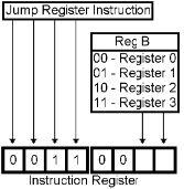
The computer is executing a series of instructions in RAM, one after the other, and suddenly one of those instructions changes the contents of the IAR. What will happen then? The next instruction that will be fetched will not be the one that follows the last one. It will be the one that is at whatever RAM address was loaded into the IAR. And it will carry on from that point with the next one, etc. until it executes another jump instruction.
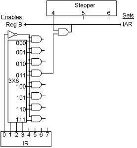
The wiring for the Jump Register instruction only needs one step. In step 4, the selected register is enabled onto the bus, and set into the IAR, and that is all. If we wanted to speed up our CPU, we could use step 5 to reset the stepper. But to keep our diagram simple, we won’t bother with that. Steps 5 an 6 will do nothing.
Here is another new word for our computer language:
Language | Meaning | |
JMPR | RB | Jump to the address in RB |
Another Way to Jump
This is another type of Jump instruction. It is similar to the Data instruction in that it uses two bytes. It replaces the IAR with the byte that is in RAM immediately following the instruction byte, thus changing where in RAM the next and subsequent instructions will come from. Here is the Instruction Code for it. Bits 4, 5, 6 and 7 are not used in this instruction:
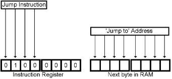
This exact type of Jump instruction is just called a “Jump.” It is useful when you know the address that you are going to want to jump to, when you are writing the program. The Jump Register Instruction is more useful when the address you are going to want to jump to is calculated as the program in running, and may not always be the same.
One of the things you can do with a Jump instruction is to create a loop of instructions that execute over and over again. You can have a series of fifty instructions in RAM, and the last instruction “Jumps” back to the first one.
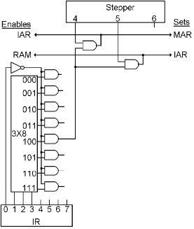
Like the Data instruction, the IAR already points to the byte we need. Unlike the Data Instruction, we don’t need to add 1 to the IAR a second time because we are going to replace it anyway. So we only need two steps. In step 4, we send IAR to MAR. In step 5 we move the selected RAM byte to the IAR. Step 6 will do nothing.
Here is the wiring that makes it work:
Here is another new word for our computer language:
Language | Meaning | |
JMP | Addr | Jump to the address in the next byte |
The Third Great Invention
Here is the third, and last, invention that makes a computer a computer.
This is just like the Jump Instruction, but sometimes it jumps, and sometimes it doesn’t. Of course, to jump or not to jump is just two possibilities, so it only takes one bit to determine which will happen. Mostly what we are going to introduce in this chapter is where that one bit comes from.
Do you remember the ‘Carry’ bit that comes out of, and goes back into the ALU? This bit comes either from the adder, or from one of the shifters. If you add two numbers that result in an amount that is greater than 255, the carry bit will come on. If you left shift a byte that has the left bit on, or right shift a byte that has the right bit on, these situations will also turn on the ALU’s carry out bit.
There is also a bit that tells us if the two inputs to the ALU are equal, another one that tells us if the A input is larger, and one more bit that tells us if the output of the ALU is all zeros.
These bits are the only things that we have not yet found a home for in the CPU. These four bits will be called the “Flag” bits, and they will be used to make the decision for a “Jump If” instruction as to whether it will execute the next instruction in RAM or jump to some other address.
What we are trying to get the computer to be able to accomplish, is for it to first execute an ALU instruction, and then have one or more “Jump If” instructions following it. The “Jump If” will jump or not depending on something that happened during the ALU instruction.
Of course, by the time the “Jump If” is executing, the results of the ALU instruction are long gone. If you go back and look at the details of the ALU instruction, it is only during step 5 that all of the proper inputs are going into the ALU and the desired answer is coming out. It is at this time that the answer is set into ACC. The timing is the same for all four Flag bits, they are only valid during step 5 of the ALU instruction. Therefore, we need a way to save the state of the Flag bits as they were during step 5 of the ALU instruction.
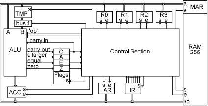
Here is the last register that we are going to add to the CPU. This will be called the FLAG register, and we are only going to use four bits of it, one for each of the flags.
The Flag bits from the ALU are connected to the input of this register, and it will be set during step 5 of the ALU instruction just like ACC and it will stay set that way until the next time an ALU instruction is executed. Thus if you have an ALU instruction followed by a “Jump If” instruction, the “Flag” bits can be used to “decide” whether to Jump or not.
Every instruction cycle uses the ALU in step 1 to add 1 to the address for the next instruction, but only step 5 of the ALU instruction has a connection that sets the Flags. (We did not show this connection in the wiring for the ALU instruction because we had not yet introduced the Flag Reg, but it will appear in the completed Control Section diagram.)
This combination of Flag bits, and the Jump IF instruction, is the third and last great invention that makes computers as we know them today, work.
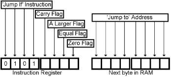
Here is the Instruction Code for a ‘Jump If’ instruction. The second four bits of the instruction tell the CPU which flag or flags should be checked. You put a ‘1’ in the instruction bit(s) corresponding to the flag(s) that you want to test for. If any one of the Flags that you test is on, the jump will happen. This arrangement gives us a number of ways to decide whether to jump or not. There is a second byte that contains the address to jump to, if the jump is taken.
Here is the wiring in the Control Section that makes the Jump If instruction work.
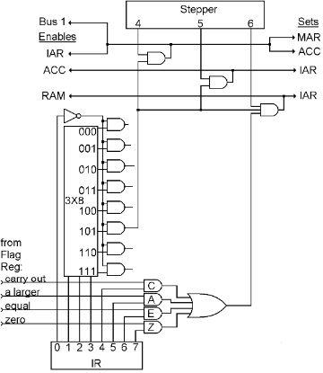
Step 4 moves IAR to MAR so we are prepared to get the ‘Jump to Address’ that we will use IF we jump. But because we might not jump, we also need to calculate the address of the next instruction in RAM. And so step 4 also turns on Bus 1 and sets the answer in ACC.