But How Do It Know? - the Basic Principles of Computers for Everyone (13 page)
Read But How Do It Know? - the Basic Principles of Computers for Everyone Online
Authors: J Clark Scott

Since the input and the output are both eight wires, we’ll simplify by using our bus type picture.
The ANDer
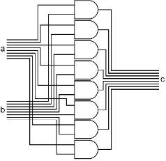
The ANDer takes two input bytes, and ANDs each bit of those two into a third byte. As you can see, the eight bits of the ‘a’ input bus are connected to the upper side of eight AND gates. The eight bits of the ‘b’ input bus are connected to the lower side of the same eight AND gates. The outputs of the eight AND gates form the bus output ‘c’ of this assembly. With this, we can AND two bytes together to form a third byte.
There are many uses for this. For example, you can make sure that an ASCII letter code is uppercase. If you have the code for the letter ‘e’ in R0, 0110 0101, you could put the bit pattern 1101 1111 into R1 and then AND R1 and R0 and put the answer back into R0. All of the bits that were on in R0 will be copied back to R0 except for the third bit. Whether the third bit had been on or off before, it will now be off. R0 will now contain 0100 0101, the ASCII code for ‘E.’ This works for all ASCII letter codes because of the way ASCII is designed.
Here is a simpler bus type picture for the ANDer.

The ORer
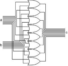
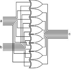
The ORer takes two input bytes, and ORs each bit of those two into a third byte. As you can see, the eight bits of the ‘a’ input bus are connected to the upper side of eight OR gates. The eight bits of the ‘b’ input bus are connected to the lower side of the same eight OR gates. The outputs of the eight OR gates are the bus output ‘c’ of this assembly. With this, we can OR two bytes together to form a third byte.
What is the use of this? There are many, but here is one of them. Say you have the ASCII code for the letter ‘E’ in R0, 0100 0101. If you want to make this letter be lowercase, you could put the bit pattern 0010 0000 into R1 and then OR R0 and R1 and put the answer back into R0. What will happen? All of the bits of R0 will be copied back into R0 as they were except the third bit will now be on no matter what it had been. R0 will now be 0110 0101, the ASCII code for ‘e.’ This will work no matter what ASCII letter code was in R0 because of the way ASCII was designed.
Here is a simpler bus type picture for the ORer.

The Exclusive ORer
The XORer takes two input bytes, and XORs each bit of those two into a third byte. As you can see, the eight bits of the ‘a’ input bus are connected to the upper side of eight XOR gates. The eight bits of the ‘b’ input bus are connected to the lower side of the same eight XOR gates. The outputs of the eight XOR gates are the bus output ‘c’ of this assembly. With this, we can XOR two bytes together to form a third byte.
What is the use of this? Again, imaginative people have come up with many of uses. But here is one of them. Say you have one code in R1 and another code in R2. You want to find out if those two codes are the same. So you XOR R1 and R2 into R1. If R1 and R2 contained the same patterns, then R1 will now be all zeros. It doesn’t matter what pattern of 0s and 1s was in R1, if R2 contained the same pattern, after an XOR, R1 will be all zeros.
Since both of the inputs and the output are all eight wires, we’ll simplify by using our bus type picture.

The Adder
This is a combination of gates that is surprisingly simple considering what it does. In our binary number system, we have numbers in the range of 0 to 255 represented in a byte. If you think about how addition is done with two of our regular decimal numbers, you start by adding the two numbers in the right column. Since the two numbers could each be anywhere from 0 to 9, the sum of these two will be somewhere from 0 to 18. If the answer is anywhere from 0 to 9, you write it down below the two numbers. If the answer is from 10 to 18, you write down the right digit, and carry the 1 to add to the next column to the left.
2 5
+4
+7
6 12
In the binary number system, it is actually much simpler. If you do the same type of addition in binary, the two numbers in the right column can each only be 0 or 1. Thus the only possible answers for adding the right column of two binary numbers will be 0, 1 or 10 (zero, one or two). If you add 0+0, you get 0, 1+0 or 0+1 you get 1, 1+1 you get 0 in the right column, and carry 1 to the column to the left.
1 1
+0
+1
1 10
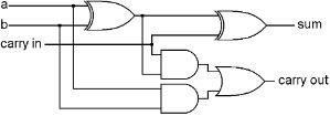
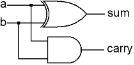
The gates we have described can easily do this. An XOR of the two bits will tell us what the right column answer should be, and an AND of the two bits will tell us whether we need to carry a 1 to the column on the left. If one bit is on, and the other one is off, that is, we are adding a 1 and a 0, the answer for the right column will be 1. If both numbers are 1, or both numbers are 0, the right column will be 0. The AND gate turns on only in the case where both input numbers are 1.
So we have added the right column easily. Now we want to add the next column to the left. Should be the same, right? There are two bits that could be 0 or 1, but this time we also have the possibility of a carry from the previous column. So it’s not the same, this time we are really adding three numbers, the two bits in this column, plus the possible carry from the previous column.
Carry-> | 0 | 1 | 0 | 1 1 |
00 | 01 | 10 | 011 | |
+01 | +01 | +01 | +011 | |
01 | 10 | 11 | 110 |
When adding three bits, the possible answers are 0, 1, 10 or 11 (zero, one, two or three.) It is more complex, but not impossible. Here is the combination that does it: