But How Do It Know? - the Basic Principles of Computers for Everyone (23 page)
Read But How Do It Know? - the Basic Principles of Computers for Everyone Online
Authors: J Clark Scott

Why does NOTting and ADDing result in subtraction? Why do you have to add 1 after NOTting? Why do you ignore the carry bit? We are not going to attempt to answer any of these questions in this book. These are the details that keep a very few engineers from getting a good night’s sleep. These brave people study these problems and design ways for ordinary people to not have to understand it.
Here is how you do multiplication. When we do multiplication with a pencil and paper in the decimal system, you have to remember your multiplication tables, you know, 3 times 8 equals 24, 6 times 9 equals 54, etc.
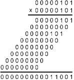
In binary, multiplication is actually much easier than in decimal. 1 times 1 equals 1, and for every other combination, the answer is 0! It just couldn’t get much simpler than that! Here’s an example of multiplying 5 times 5 with pencil and paper in binary.

If you look at what’s happening here, if the right digit of the bottom number is a 1, you put the top number in the answer. Then, for every digit to the left of that, shift the top number left, and if the bottom digit is a 1, add the shifted top number to the answer. When you get through the eight bits of the bottom number, you’re done.
So multiplication is accomplished with the adder and the shifters. It’s as simple as that. You can write a simple program like this:
R0 contains the bottom number, R1 contains the top number and R2 will contain the answer. R3 is used to jump out of the loop after going through it eight times.
RAM Addr | Instruction | Comments | |
50 | DATA | R3,0000 0001 | * Put ‘1’ into R3 |
52 | XOR | R2,R2 | * Put ‘0’ in R2 |
53 | CLF | * Clear Flags | |
54 | SHR | R0 | * One bit to Carry Flag |
55 | JC | 59 | * Do the ADD |
57 | JMP | 61 | * Skip the ADD |
59 | CLF | * Clear Flags | |
60 | ADD | R1,R2 | * ADD this line |
61 | CLF | * Clear Flags | |
62 | SHL | R1 | * Mult top by 2 |
63 | SHL | R3 | * Shift counter |
64 | JC | 68 | * Out if done |
66 | JMP | 53 | * Do next step |
68 | (Next instruction in program) |
See what happens with the Registers as this program goes through its loop the first three times.
R0 R1 R2 R3
At start (after 52):
0000 0101 0000 0101 0000 0000 0000 0001
First time (after 63):
0000 0010 0000 1010 0000 0101 0000 0010
Second time (after 63):
0000 0001 0001 0100 0000 0101 0000 0100
Third time (after 63):
0000 0000 0010 1000 0001 1001 0000 1000
The important thing that has happened here is that R1 has been added to R2 twice. It happened on the first time through, when R1 contained 0000 0101, and on the third time through, after R1 had been shifted left twice and therefore contained 0001 0100. R2 now contains 0001 1001 binary, which is 16+8+1, or 25 decimal, which is the correct answer for 5 times 5. The loop will repeat 5 more times until the bit in R3 gets shifted out to the Carry Flag, but the total won’t increase because there are no more 1s in R0.
This program will go through eight times. We start with 0000 0001 in R3. Near the end of the program, R3 gets shifted left. The first seven times through, there will be no carry, so the program will get to the ‘JMP 53’ and go back up to the third instruction of the program. The eighth time R3 gets shifted left, the one bit that is on gets shifted out of R3 and into the Carry flag. Therefore, the ‘JC 68’ will jump over the ‘JMP 53’ and carry on with whatever instructions come after this.
The byte in R0 gets shifted right to test which bits are on. The byte in R1 gets shifted left to multiply it by two. When there was a bit in R0, you add R1 to R2. And that’s all there is to it.
One thing we do not address in this example is what happens if the answer of the multiplication is more than 255. If a multiplication program multiplies two one-byte numbers, it ought to be able to handle a two-byte answer. That would take care of any two numbers that you might start with. This would be accomplished with the carry flag and some more Jump If instructions. We won’t torture the reader with the details.
Reading a program like the one above is an entirely different skill than reading the diagrams and graphs we have seen so far in the book. I hope you were able to follow it, but no one is expected to become an expert at reading programs because of this book.
Division also can be done by our computer. There are several ways it can be done, and we are not going to examine any of them in any detail. Just imagine the following simple method. Lets say you want to divide fifteen by three. If you repeatedly subtract three from fifteen, and count the number of subtractions you can accomplish before the fifteen is all gone, that count will be the answer. Like these five steps: (1)15-3=12, (2)12-3=9, (3)9-3=6, (4)6-3-3, (5)3-3=0. This is easily turned into a program.
Computers also have ways of handling negative numbers and numbers with decimal points. The details are very tedious, and studying them would not enhance our understanding of how computers work. It still comes down to nothing more than NAND gates. Our simple computer could do all of these things with programs.
The Outside World
What we have described so far is the whole computer. It has two parts, the RAM and the CPU. That’s all there is. These simple operations are the most complicated things that a computer can do. The ability to execute instructions, modify bytes with the ALU, the ability to jump from one part of the program to another, and most importantly, the ability to jump or not jump based on the result of a calculation. This is what a computer is able to do. These are simple things, but since it operates so quickly, it can do huge numbers of these operations that can result in something that looks impressive.
These two parts make it a computer, but if all the computer could do is run a program and rearrange bytes in RAM, no one would ever know what it was doing. So there is one more thing that the computer needs in order to be useful, and that is a way to communicate with the outside world.
Dealing with anything outside of the computer is called ‘Input/Output’ or ‘I/O’ for short. Output means data going out of the computer; Input means data coming into the computer. Some things are input only, such as a keyboard, some things are output only, like a display screen, some things do both input and output, like a disk.
All we need for I/O is a few wires, and a new instruction.
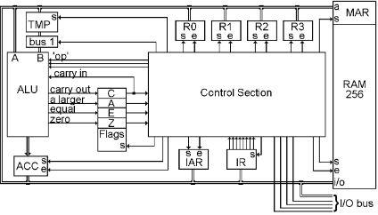
For the wires, all we are going to do is to extend the CPU bus outside of the computer and add four more wires to go with it. This combination of 12 wires will be called the I/O Bus. Everything that is connected to the computer is attached to this one I/O bus.
The devices that are connected to the I/O bus are called ‘peripherals,’ because they are not inside the computer, they are outside of the computer, on its periphery (the area around it.)
More than one thing can be attached to the I/O bus, but the computer controls the process, and only one of these things is active at a time.
Each thing attached to the I/O bus has to have its own unique I/O address. This is not the same as the addresses of the bytes in RAM, it is just some ‘number’ that the peripheral will recognize when placed on the bus.
Here is what the I/O bus looks like in the CPU, there at the bottom right of the drawing.

In the diagram below are the wires of the I/O Bus. The CPU Bus is the same eight-wire bundle that goes everywhere else. The ‘Input/Output’ wire determines which direction data will be moving on the CPU bus, either in or out. The ‘Data/Address’ wire tells us whether we will be transferring a byte of data, or an I/O Address that selects one of the many devices that could be attached to the I/O bus. ‘I/O Clk e’ and ‘I/O Clk s’ are used to enable and set registers so that bytes can be moved back and forth.

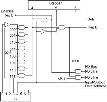
Here is the control section wiring for the new instruction that controls the I/O bus. This shows where the four new wires for the I/O bus come from. They are at the bottom right of the drawing. They were also shown on the full control section diagram a few chapters back. Sorry if that was confusing, but having that diagram in the book once was enough.

IR bits 4 and 5 are placed on the I/O bus at all times. To make the I/O operation happen, only one step is needed. For Output, Reg B is enabled, and I/O Clk s is turned on and off during step 4. Steps 5 and 6 do nothing. For Input, I/O Clk e is enabled, and Reg B is set during step 5. Steps 4 and 6 do nothing.
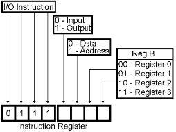
Here is the Instruction Code for the I/O instruction:
