Make: Electronics (10 page)
Authors: Charles Platt

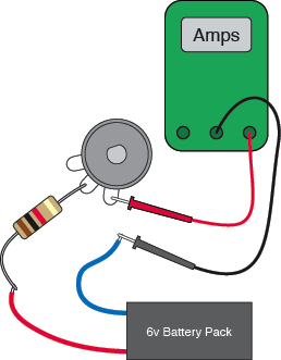
Figure 1-64.
If you substitute a resistor instead of the LED, you can confirm that the current flowing through the circuit varies with the total resistance in the circuit, if the voltage stays the same.
Turn the potentiometer all the way counterclockwise, and you have a total of 3K resistance in the circuit. Your meter should show about 2 mA flowing. Now turn the potentiometer halfway, and you have about 2K total resistance. You should see about 3 mA flowing. Turn the potentiometer all the way clockwise, so there’s a total of 1K, and you should see 6 mA flowing. You may notice that if we multiply the resistance by the amperage, we get 6 each time—which just happens to be the voltage being applied to the circuit. See the following table.
Total resistance | Current | Voltage |
(KΩ) | (mA) | (Volts) |
3 | 2 | 6 |
2 | 3 | 6 |
1 | 6 | 6 |
In fact, we could say:
voltage = kilohms × milliamps
But wait a minute: 1K is 1,000 ohms, and 1mA is 1/1,000 of an amp. Therefore, our formula should really look like this:
voltage = (ohms × 1,000) × (amps/1,000)
The two factors of 1,000 cancel out, so we get this:
volts = ohms × amps
This is known as Ohm’s Law. See the section, “Fundamentals: Ohm’s Law,” on the following page.
Fundamentals
Series and parallel
Before we go any further, you should know how resistance in a circuit increases when you put resistors in series or in parallel. Figures 1-65 through 1-67 illustrate this. Remember:
- Resistors in series are oriented so that one follows the other.
- Resistors in parallel are oriented side by side.
When you put two equal-valued resistors in series, you double the total resistance, because electricity has to pass through two barriers in succession.
When you put two equal-valued resistors in parallel, you divide the total resistance by two, because you’re giving the electricity two paths which it can take, instead of one.
In reality we don’t normally need to put resistors in parallel, but we often put other types of components in parallel. Lightbulbs in your house, for instance, are all wired that way. So, it’s useful to understand that resistance in a circuit goes down if you keep adding components in parallel.
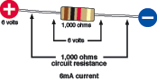
Figure 1-65.
One resistor takes the entire voltage, and according to Ohm’s Law, it draws v/R = 6/1,000 = 0.006 amps = 6mA of current.
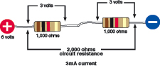
Figure 1-66.
When two resistors are in series, the electricity has to pass through one to reach the other, and therefore each of them takes half the voltage. Total resistance is now 2,000 ohms, and according to Ohm’s Law, the circuit draws v/R = 6/2,000 = 0.003 amps = 3mA of current.
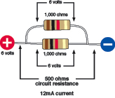
Figure 1-67.
When two resistors are in parallel, each is exposed to the full voltage, so each of them takes 6 volts. The electricity can now flow through both at once, so the total resistance of the circuit is half as much as before. According to Ohm’s Law, the circuit draws v/R = 6/500 = 0.012 amps = 12mA of current.
Using Ohm’s Law
Ohm’s Law is extremely useful. For example, it helps us to figure out whether a component can be used safely in a circuit. Instead of stressing the component until we burn it out, we can predict whether it will work.
For instance, the first time you turned the potentiometer, you didn’t really know how far you could go until the LED burned out. Wouldn’t it be useful to know precisely what resistance to put in series with an LED, to protect it adequately while providing as much light as possible?
Fundamentals
Ohm’s Law
For reasons I’ll explain in a moment, amps are normally abbreviated with the letter I. V stands for volts and R stands for resistance in ohms (because the omega symbol, Ω, is not easily generated from most keyboards). Using these symbols, you can write Ohm’s Law in three different ways:
V = I × R
I = V/R
R = V/I
Remember, V is a
difference
in voltage between two points in a simple circuit, R is the resistance in ohms
between
the same two points, and I is the current in amps flowing
through
the circuit between the two points.
Letter I is used because originally current was measured by its
inductance
, meaning the ability to induce magnetic effects. It would be much less confusing to use A for amps, but unfortunately it’s too late for that to happen.
How to Read a Data Sheet
Like most information, the answer to this question is available online.
Here’s how you find a manufacturer’s data sheet (Figure 1-68). First, find the component that you’re interested in from a mail-order source. Next, Google the part number and manufacturer’s name. Usually the data sheet will pop up as the first hit. A source such as
Mouser.com
makes it even easier by giving you a direct link to manufacturers’ data sheets for many products.
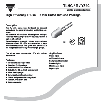
Figure 1-68.
The beginning of a typical data sheet, which includes all relevant specifications for the product, freely available online.
Background
How much voltage does a wire consume?
Normally, we can ignore the resistance in electric wires, such as the little leads of wire that stick out of resistors, because it’s trivial. However, if you try to force large amounts of current through long lengths of thin wire, the resistance of the wire can become important.
How important? Once again, we can use Ohm’s Law to find out.
Suppose that a very long piece of wire has a resistance of 0.2Ω. And we want to run 15 amps through it. How much voltage will the wire steal from the circuit, because of its resistance?
Once again, you begin by writing down what you know:
R = 0.2
I = 15
We want to know V, the potential difference, for the wire, so we use the version of Ohm’s Law that places V on the left side:
V = I × R
Now plug in the values:
V = 15 × 0.2 = 3 volts
Three volts is not a big deal if you have a high-voltage power supply, but if you are using a 12-volt car battery, this length of wire will take one-quarter of the available voltage.
Now you know why the wiring in automobiles is relatively thick—to reduce its resistance well below 0.2Ω. See Figure 1-69.
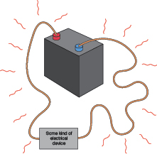
Figure 1-69.
When a 12-volt car battery runs some kind of electrical device through a long piece of thin wire, the resistance of the wire steals some of the voltage and dissipates it as heat.
Here’s an example. Suppose I want a red LED, such as the Vishay part TLHR5400, which has become such a common item that I can buy them individually for 9 cents apiece. I click the link to the data sheet maintained by the manufacturer, Vishay Semiconductor. Almost immediately I have a PDF page on my screen. This data sheet is for TLHR, TLHG, and TLHY types of LED, which are red, green, and yellow respectively, as suggested by the R, G, and Y in the product codes. I scroll down and look at the “Optical and Electrical Characteristics” section. It tells me that under conditions of drawing a current of 20 mA, the LED will enjoy a “Typ,” meaning, typical, “forward voltage” of 2 volts. The “Max,” meaning maximum, is 3 volts.