Make: Electronics (8 page)
Authors: Charles Platt

Swap out the 1K resistor and substitute a 470Ω resistor, which will have yellow-violet-brown stripes, meaning 4-7 and one more zero. The LED should be brighter still.
This may seem very elementary, but it makes an important point. The resistor blocks a percentage of the voltage in the circuit. Think of it as being like a kink or constriction in a flexible hose. A higher-value resistor blocks more voltage, leaving less for the LED.
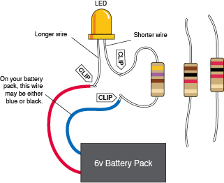
Figure 1-45.
Here’s how it actually looks, using a large LED. If you start with the highest value resistor, the LED will glow very dimly as you complete the circuit. The resistor drops most of the voltage, leaving the LED with insufficient current to make it shine brightly.
Cleanup and Recycling
We’ll use the batteries and the LED in the next experiment. The resistors can be reused in the future.
Experiment 4: Varying the Voltage
Potentiometers come in various shapes and sizes, but they all do the same thing: they allow you to vary voltage and current by varying resistance. This experiment will enable you to learn more about voltage, amperage, and the relationship between them. You’ll also learn how to read a manufacturer’s data sheet.
You will need the same batteries, battery carrier, alligator clips, and LED from the last experiment, plus:
- Potentiometer, 2KΩ linear. Quantity: 2. (See Figure 1-46.) Full-sized potentiometers that look like this are becoming less common, as miniature versions are taking their place. I’d like you to use a large one, though, because it’s so much easier to work with.
- One extra LED.
- Multimeter.
Look Inside Your Potentiometer
The first thing I want you to do is find out how a potentiometer works. This means you’ll have to open it, which is why your shopping list required you to buy two of them, in case you can’t put the first one back together again.
Most potentiometers are held together with little metal tabs. You should be able to grab hold of the tabs with your wire cutters or pliers, and bend them up and outward. If you do this, the potentiometer should open up as shown in Figures 1-47 and 1-48.
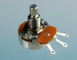
Figure 1-46
.
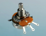
Figure 1-47
.
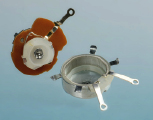
Figure 1-48.
To open the potentiometer, first pry up the four little metal tabs around the edge (you can see one sticking out at the left and another one sticking out at the right in Figure 1-47). Inside is a coil of wire around a flat plastic band, and a pair of springy contacts (the wiper), which conduct electricity to or from any point in the coil when you turn the shaft.
Depending whether you have a really cheap potentiometer or a slightly more high-class version, you may find a circular track of conductive plastic or a loop of coiled wire. Either way, the principle is the same. The wire or the plastic possesses some resistance (a total of 2K in this instance), and as you turn the shaft of the potentiometer, a wiper rubs against the resistance, giving you a shortcut to any point from the center terminal.
You can try to put it back together, but if it doesn’t work, use your backup potentiometer instead.
To test your potentiometer, set your meter to measure resistance (ohms) and touch the probes while turning the potentiometer shaft to and fro, as shown in Figure 1-49.
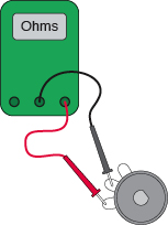
Figure 1-49.
Measure the resistance between these two terminals of the potentiometer while you turn its shaft to and fro.
Dimming Your LED
Begin with the potentiometer turned all the way counterclockwise, otherwise you’ll burn out the LED before we even get started. (A very, very small number of potentiometers increase and decrease resistance in the opposite way to which I’m describing here, but as long as your potentiometer looks like the one in Figure 1-48 after you open it up, my description should be accurate.)
Now connect everything as shown in Figures 1-50 and 1-51, taking care that you don’t allow the metal parts of any of the alligator clips to touch each other. Now turn up the potentiometer
very
slowly. You’ll notice the LED glowing brighter, and brighter, and brighter—until, oops, it goes dark. You see how easy it is to destroy modern electronics? Throw away that LED. It will never glow again. Substitute a new LED, and we’ll be more careful this time.
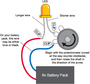
Figure 1-50.
The setup for
Experiment 4
. Rotating the shaft of the 2K potentiometer varies its resistance from 0 to 2,000Ω. This resistance protects the LED from the full 6 volts of the battery.
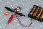
Figure 1-51.
The LED in this photo is dark because I turned the potentiometer up just a little bit too far.
While the batteries are connected to the circuit, set your meter to measure
volts DC
as shown in Figures 1-52 through 1-54. Now touch the probes either side of the LED. Try to hold the probes in place while you turn the potentiometer up a little, and down a little. You should see the voltage pressure around the LED changing accordingly. We call this the
potential difference
between the two wires of the LED.
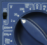
Figure 1-52
.
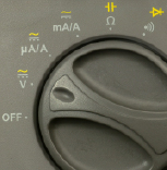
Figure 1-53
.