Make: Electronics (52 page)
Authors: Charles Platt

We’re getting close to a final working circuit here. We can reset the count to zero (with S3), start the count (with S5), and wait for the user to stop the count (with S4). The only thing missing is a way to start the count unexpectedly.
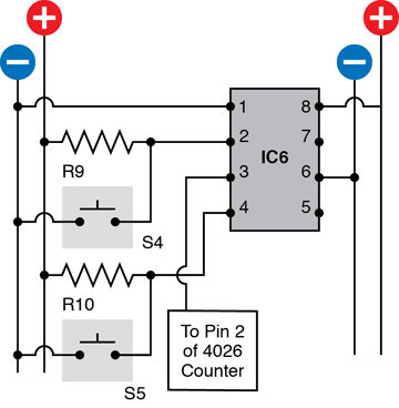
Figure 4-40.
Adding a bistable 555 timer to the reflex tester will stop the counter with a touch of a button, and keep it stopped.
R9, R10: 1K
IC6: 555 timer
The Delay
Suppose we set up yet another 555 in monostable mode. Trigger its pin 2 with a negative pulse, and the timer delivers a positive output that lasts for, say, 4 seconds. At the end of that time, its output goes back to being negative. Maybe we can hook that positive-to-negative transition to pin 4 of IC6. We can use this instead of switch S5, which you were pressing previously to start the count.
Check the new schematic in Figure 4-41 which adds another 555 timer, IC7 above IC6. When the output from IC7 goes from positive to negative, it will trigger the reset of IC6, flipping its output negative, which allows the count to begin. So IC7 has taken the place of the start switch, S4. You can get rid of S4, but keep the pull-up resistor, R9, so that the reset of IC6 remains positive the rest of the time.
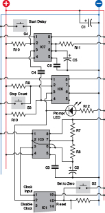
Figure 4-41.
The completed control section of the circuit, to be added above these timers.
R7, R9, R10, R12: 1K
R8: 2K2
R11: 330K
C1: 100 µF
C2: 68 µF
C3, C4, C6: 0.1 µF
C5: 10 µF
S1, S2, S3: tactile switches
IC5, IC6, IC7: 555 timers
This arrangement works because I have used a capacitor, C4, to connect the output of IC7 to the reset of IC6. The capacitor communicates the sudden change from positive to negative, but the rest of the time it blocks the steady voltage from IC7 so that it won’t interfere with IC6.
The final schematic in Figure 4-41 shows the three 555 timers all linked together, as you should insert them above the topmost counter, IC1. I also added an LED to signal the user. Figure 4-42 is a photograph of my working model of the circuit.
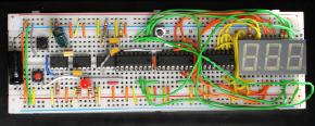
Figure 4-42.
The complete reaction-timer circuit barely fits on a 63-row breadboard.
Because this circuit is complicated, I’ll summarize the sequence of events when it’s working. Refer to Figure 4-41 while following these steps:
1.
User presses Start Delay button S4, which triggers IC7.
2.
IC7 output goes high for a few seconds while C5 charges.
3.
IC7 output drops back low.
4.
IC7 communicates a pulse of low voltage through C4 to IC6, pin 4.
5.
IC 6 output flips to low and flops there.
6.
Low output from IC6 sinks current through LED and lights it.
7.
Low output from IC6 also goes to pin 2 of IC1.
8.
Low voltage on pin 2 of IC1 allows IC1 to start counting.
9.
User presses S3, the “stop” button.
10.
S3 connects pin 2 of IC6 to ground.
11.
IC6 output flips to high and flops there.
12.
High output from IC6 turns off the LED.
13.
High output from IC6 also goes to pin 2 of IC1.
14.
High voltage on pin 2 of IC1 stops it from counting.
15.
After assessing the result, user presses S2.
16.
S2 applies positive voltage to pin 15 of IC1, IC2, IC3.
17.
Positive voltage resets counters to zero.
18.
The user can now try again.
19.
Meanwhile, IC5 is running continuously throughout.
In case you find a block diagram easier to understand, I’ve included that, too, in Figure 4-43.

Figure 4-43.
The functions of the reflex tester, summarized as a block diagram.
Using the Reflex Tester
At this point, you should be able to test the circuit fully. When you first switch it on, it will start counting, which is slightly annoying, but easily fixed. Press S3 to stop the count. Press S2 to reset to zero.
Now press S4. Nothing seems to happen—but that’s the whole idea. The delay cycle has begun in stealth mode. After a few seconds, the delay cycle ends, and the LED lights up. Simultaneously, the count begins. As quickly as possible, the user presses S3 to stop the count. The numerals freeze, showing how much time elapsed.
There’s only one problem—the system has not yet been calibrated. It is still running in slow-motion mode. You need to change the resistor and capacitor attached to IC5 to make it generate 1,000 pulses per second instead of just three or four.
Substitute a 10K trimmer potentiometer for R8 and a 1 µF capacitor for C2. This combination will generate about 690 pulses per second when the trimmer is presenting maximum resistance. When you turn the trimmer down to decrease its resistance, somewhere around its halfway mark the timer will be running at 1,000 pulses per second.
How will you know exactly where this point is? Ideally, you would attach an oscilloscope probe to the output from IC5. But, most likely, you don’t have an oscilloscope, so here are a couple other suggestions.
First remove the 1 µF capacitor at C2 and substitute a 10 µF capacitor. Because you are multiplying the capacitance by 10, you will reduce the speed by 10. The leftmost digit in your display should now count in seconds, reaching 9 and rolling over to 0 every 10 seconds. You can adjust your trimmer potentiometer while timing the display with a stopwatch. When you have it right, remove the 10 µF capacitor and replace the 1 µF capacitor at C2.
The only problem is, the values of capacitors may be off by as much as 10%. If you want to fine-tune your reflex timer, you can proceed as follows.
Disconnect the wire from pin 5 of IC3, and substitute an LED with a 1K series resistor between pin 5 and ground. Pin 5 is the “carry” pin, which will emit a positive pulse whenever IC3 counts up to 9 and rolls over to start at 0 again. Because IC3 is counting tenths of a second, you want its carry output to occur once per second.
Now run the circuit for a full minute, using your stopwatch to see if the flashing LED drifts gradually faster or slower than once per second. If you have a camcorder that has a time display in its viewfinder, you can use that to observe the LED.
If the LED flashes too briefly to be easily visible, you can run a wire from pin 5 to another 555 timer that is set up in monostable mode to create an output lasting for around 1/10 of a second. The output from that timer can drive an LED.
Enhancements
It goes without saying that anytime you finish a project, you see some opportunities to improve it. Here are some suggestions:
1.
No counting at power-up. It would be nice if the circuit begins in its “ready” state, rather than already counting. To achieve this you need to send a negative pulse to pin 2 of IC6, and maybe a positive pulse to pin 15 of IC1. Maybe an extra 555 timer could do this. I’m going to leave you to experiment with it.
2.
Audible feedback when pressing the Start button. Currently, there’s no confirmation that the Start button has done anything. All you need to do is buy a piezoelectric beeper and wire it between the righthand side of the Start button and the positive side of the power supply.
3.
A random delay interval before the count begins. Making electronic components behave randomly is very difficult, but one way to do it would be to require the user to hold his finger on a couple of metal contacts. The skin resistance of the finger would substitute for R11. Because the finger pressure would not be exactly the same each time, the delay would vary. You’d have to adjust the value of C5.
Summing Up
This project demonstrated how a counter chip can be controlled, how counter chips can be chained together, and three different functions for 555 timers. It also showed you how chips can communicate with each other, and introduced you to the business of calibrating a circuit after you’ve finished building it.
Naturally, if you want to get some practical use from the circuit, you should build it into an enclosure with heavier-duty pushbuttons—especially the button that stops the count. You’ll find that when people’s reflexes are being tested, they are liable to hit the stop button quite hard.
Because this was a major project, I’ll follow it up here with some quicker, easier ones as we move into the fascinating world of another kind of integrated circuit: logic chips.
Experiment 19: Learning Logic
You will need:
- Assorted resistors and capacitors.
- 74HC00 quad 2-input NAND chip, 74HC08 quad 2-input AND chip, and LM7805 voltage regulator. Quantity: 1 of each.
- Signal diode, 1N4148 or similar. Quantity: 1.
- Low-current LED. Quantity: 1.
- SPST tactile switches. Quantity: 2.
You’re going to be entering the realm of pure digital electronics, using “logic gates” that are fundamental in every electronic computing device. When you deal with them individually, they’re extremely easy to understand. When you start chaining them together, they can seem intimidatingly complex. So let’s start with them one at a time.
Logic gates are much fussier than the 555 timer or the 4026 counter that you used previously. They demand an absolutely precise 5 volts DC, with no fluctuations or “spikes” in the flow of current. Fortunately, this is easy to achieve: just set up your breadboard with an LM7805 voltage regulator, as shown in the schematic in Figure 4-44 and the photograph in Figure 4-45. The regulator receives 9 volts from your usual voltage supply, and reduces it to 5 volts, with the help of a couple of capacitors. You apply the 9 volts to the regulator, and distribute the 5 volts down the sides of your breadboard instead of the unregulated voltage that you used previously. Use your meter to verify the voltage, and make sure you have the polarity clearly marked.