Make: Electronics (22 page)
Authors: Charles Platt

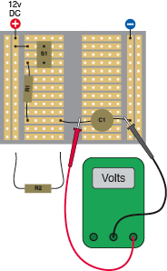
Figure 2-78.
Watch the voltage building up on the capacitor while you hold down the pushbutton. Substitute other values for R1, discharge the capacitor by touching R2 across it, and then repeat your measurement process.
S1: Momentary pushbutton, OFF (ON)
R1: 100K initially
R2: 100Ω
C1: 1,000 µF
Release the pushbutton, set aside your meter, and discharge the capacitor by touching R2 across it for a second or two. Now substitute a 50K resistor for R1, and repeat the measurement. The meter should count upward almost twice as fast as before.
Voltage, Resistance, and Capacitance
Think of the resistor as a faucet, and the capacitor as a balloon that you are trying to fill with water. When you screw down the faucet until only a trickle comes through, the balloon will take longer to fill. But a slow flow of water will still fill the balloon completely if you wait long enough, and (assuming the balloon doesn’t burst) the process ends when the pressure inside the balloon is equal to the water pressure in the pipe supplying the faucet. See Figure 2-79.
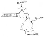
Figure 2-79.
When the faucet is closed half-way, the balloon will take longer to fill, but will still contain as much water and as much pressure in the end.
Similarly, in your circuit, if you wait long enough, eventually the voltage across the capacitor should reach the same value as the voltage of the power supply. In a 12-volt circuit, the capacitor should eventually acquire 12 volts (although “eventually” may take longer than you think).
This may seem confusing, because earlier you learned that when you apply voltage at one end of a resistor, you get less voltage coming out than you have going in. Why should a resistor deliver the full voltage when it is paired with a capacitor?
Forget the capacitor for a moment, and remember how you tested just two 1K resistors. In that situation, each resistor contained half the total resistance of the circuit, so each resistor dropped half the voltage. If you held the negative probe of your meter against the negative side of your power supply and touched the positive probe to the center point between the two resistors, you would measure 6 volts. Figure 2-80 illustrates this.
Now, suppose you remove one of the 1K resistors and substitute a 9K resistor. The total resistance in the circuit is now 10K, and therefore the 9K resistor drops 90% of the 12 volts. That’s 10.8 volts. You should try this and check it with your meter. (You are unlikely to find a 9K resistor, because this is not a standard value. Substitute the nearest value you can find.)
Now suppose you remove the 9K resistor and substitute a 99K resistor. Its voltage drop will be 99% of the available voltage, or 11.88 volts. You can see where this is heading: the larger the resistor, the larger its contribution to voltage drop.
However, I noted previously that a capacitor blocks DC voltage completely. It can accumulate an electrical charge, but no current passes through it. Therefore, a capacitor behaves like a resistor that has infinite resistance to DC current.
(Actually the insulation inside the capacitor allows a little bit of “leakage,” but a perfect capacitor would have infinite resistance.)
The value of any resistor that you put in series with the capacitor is trivial by comparison. No matter how high the value of the resistor is, the capacitor still provides much more resistance in the circuit. This means that the capacitor steals almost the complete voltage drop in the circuit, and the voltage difference between one end of the resistor and the other will be zero (assuming that we ignore little imperfections in the components). Figure 2-80 may help to clarify this concept.
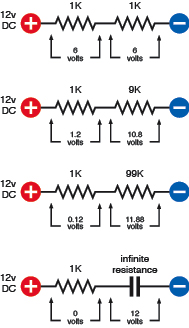
Figure 2-80.
When two resistances are in series, the larger one drops the voltage more than the smaller one. If the larger resistance becomes infinite (as in the case of a capacitor), the smaller one no longer has any measurable contribution to the voltage drop, and the voltage is almost exactly the same at both ends.
You should try this using real resistors and capacitors—although if you do, you will run into a little problem. When you use your meter in its “DC volts” mode, it diverts a little of the current in the circuit—just a tiny taste—in the process of measuring it. The meter steals such a small amount, it doesn’t affect the reading significantly when you are checking voltage across a resistor. The internal resistance of the meter is higher than the values of most resistors. However, remember that the internal resistance of a capacitor is almost infinite. Now the internal resistance of the meter becomes significant. Because you can never have an ideal meter, any more than you can have an ideal capacitor or resistor, your meter will always interfere with the circuit slightly, and you will get only an approximate indication.
If you try to measure the voltage on a capacitor that has been charged but is now not connected to anything else, you’ll see the number slowly falling, as the capacitor discharges itself through the meter.
Theory
The time constant
You may be wondering if there’s a way to predict exactly how much time it takes for various capacitors to charge, when they are paired with various resistors. Is there a formula to calculate this?
Of course, the answer is yes, but the way we measure it is a bit tricky, because a capacitor doesn’t charge at a constant rate. It accumulates the first volt very quickly, the second volt not quite as quickly, the third volt even less quickly—and so on. You can imagine the electrons accumulating on the plate of a capacitor like people walking into an auditorium and looking for a place to sit. The fewer seats that are left, the longer people take to find them.
The way we describe this is with something called a “time constant.” The definition is very simple:
TC = R × C
where TC is the time constant, in seconds, and a capacitor of C farads is being charged through a resistor of R ohms.
Going back to the circuit you just tested, try using it again, this time with a 1K resistor and the 1,000 µF capacitor. We have to change those numbers to farads and ohms before we can put them in the formula. Well, 1,000 µF is 0.001 farads, and 1K is 1,000 ohms, so the formula looks like this:
TC = 1,000 × 0.001
In other words, TC = 1—a lesson that could not be much easier to remember:
A 1K resistor in series with a 1,000 µF capacitor has a time constant of 1.
Does this mean that the capacitor will be fully charged in 1 second? No, it’s not that simple. TC, the time constant, is the time it takes for a capacitor to acquire
63%
of the voltage being supplied to it, if it starts with zero volts.
(Why 63%? The answer to that question is too complicated for this book, and you’ll have to read about time constants elsewhere if you want to know more. Be prepared for differential equations.) Here’s a formal definition for future reference:
TC, the time constant, is the time it takes for a capacitor to acquire 63% of the difference between its current charge and the voltage being applied to it. When TC=1, the capacitor acquires 63% of its full charge in 1 second. When TC=2, the capacitor acquires 63% of its full charge in 2 seconds. And so on.
What happens if you continue to apply the voltage? History repeats itself. The capacitor accumulates
another
63% of the
remaining
difference between its current charge, and the voltage being applied to it.
Imagine someone eating a cake. In his first bite he’s ravenously hungry, and eats 63% of the cake in one second. In his second bite, not wanting to seem too greedy, he takes just another 63% of the cake that is left—and because he’s not feeling so hungry anymore, he requires the same time to eat it as he took to eat the first bite. In his third bite, he takes 63% of what still remains, and still takes the same amount of time. And so on. He is behaving like a capacitor eating electricity (Figure 2-81).
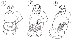
Figure 2-81.
If our gourmet always eats just 63% of the cake still on the plate, he “charges up” his stomach in the same way that a capacitor charges itself. No matter how long he keeps at it, his stomach is never completely filled.
Theory
The time constant (continued)
The cake eater will always have a few crumbs to eat, because he never takes 100% of the remainder. Likewise, the capacitor will never acquire a full charge. In a perfect world of perfect components, this process would continue for an infinite time.
In the real world, we say rather arbitrarily:
After 5 × TC the capacitor will be so nearly fully charged, we won’t care about the difference.
In the table is a calculation (rounded to two decimal places) showing the charge accumulating on a capacitor in a 12-volt circuit where the time constant is 1 second.
Here’s how to understand the table. V1 is the current charge on the capacitor. Subtract this from the supply voltage (12 volts) to find the difference. Call the result V2. Now take 63% of V2, and add this to the current charge (V1) and call the result V4. This is the new charge that the capacitor will have after 1 second, so we copy it down to the next line in the table, and it becomes the new value for V1.
Now we repeat the same process all over again. Figure 2-82 shows this in graphical form. Note that after 5 seconds, the capacitor has acquired 11.92 volts, which is 99% of the power supply voltage. This should be close enough to satisfy anyone’s real-world requirements.
Time in secs | V1: Charge on capacitor | V2: 12 – V1 | V3: 63% of V2 | V4: V1 + V3 |
0 | 0.00 | 12.00 | 7.56 | 7.56 |
1 | 7.56 | 4.44 | 2.80 | 10.36 |
2 | 10.36 | 1.64 | 1.03 | 11.39 |
3 | 11.39 | 0.61 | 0.38 | 11.77 |
4 | 11.77 | 0.23 | 0.15 | 11.92 |
5 | 11.92 |
If you try to verify these numbers by measuring the voltage across the capacitor as it charges, remember that because your meter steals a little current, there will be a small discrepancy that will increase as time passes. For practical purposes, the system works well enough.
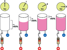
Figure 2-82.
A capacitor starts with 0 volts. After 1 time constant it adds 63% of the available voltage. After another time constant, it adds another 63% of the remaining voltage difference, and so on.