Make: Electronics (50 page)
Authors: Charles Platt

Incidentally, this display has two pins, numbered 3 and 26, both labeled to receive negative voltage for the first of the digits. Why two pins instead of one? I don’t know. You need to use only one, and as this is a passive chip, it doesn’t matter if you leave the unused one unconnected. Just take care not to apply positive voltage to it, which would create a short circuit.
A numeric display has no power or intelligence of its own. It’s just a bunch of light-emitting diodes. It’s not much use, really, until we can figure out a way to illuminate the LEDs in appropriate groups—which will be the next step.
Step 2: Counting
Fortunately, we have a chip known as the 4026, which receives pulses, counts them, and creates an output designed to work with a seven-segment display so that it shows numbers 0–9. The only problem is that this is a rather old-fashioned CMOS chip (meaning, Complementary Metal Oxide Semiconductor) and is thus sensitive to static electricity. Check the caution on
page 172
before continuing.
Switch off your power supply and connect its wires to the top of the breadboard, noting that for this experiment, we’re going to need positive and negative power on both sides. See Figure 4-34 for details. If your breadboard does not already have the columns of holes color-coded, I suggest you use Sharpie markers to identify them, to avoid polarity errors that can fry your components.

Figure 4-34.
When building circuits around chips, it’s convenient to have a positive and negative power supply down each side of your breadboard. For the reaction timer circuit, a 9V supply with a 100 µF smoothing capacitor can be set up like this. If your breadboard doesn’t color-code the columns of holes on the left and right sides, I suggest you do that yourself with a permanent marker.
The 4026 counter chip is barely powerful enough to drive the LEDs in our display when powered by 9 volts. Make sure you have the chip the right way up, and insert it into the breadboard immediately above your three-digit display, leaving just one row of holes between them empty.
The schematic in Figure 4-35 shows how the pins of the 4026 chip should be connected. The arrows tell you which pins on the display should be connected with pins on the counter.
Figure 4-36 shows the “pinouts” (i.e., the functions of each pin) of a 4026 counter chip. You should compare this with the schematic in Figure 4-35.
Include a tactile switch between the positive supply and pin 1 of the 4026 counter, with a 10K resistor to keep the input to the 4026 counter negative until the button is pressed. Make sure all your positives and negatives are correct, and turn on the power. You should find that when you tap the tactile switch lightly, the counter advances the numeric display from 0 through 9 and then begins all over again from 0. You may also find that the chip sometimes misinterprets your button-presses, and counts two or even three digits at a time. I’ll deal with this problem a little further on.
The LED segments will not be glowing very brightly, because the 1K series resistors deprive of them of the power they would really like to receive. Those resistors are necessary to avoid overloading the outputs from the counter.
 Grounding Yourself
To avoid the frustration that occurs when you power up a circuit and nothing happens, be sure to take these precautions when you use the older generation of CMOS chips (which often have part numbers from 4000 upward, such as 4002, 4020, and so on):
Chips are often shipped with their legs embedded in black foam. This is electrically conductive foam, and you should keep the chips embedded in it until you are ready to use them.
If the chips are supplied to you in plastic tubes, you can take them out and poke their legs into pieces of conductive foam or, if you don’t have any, use aluminum foil. The idea is to avoid one pin on a chip acquiring an electric potential that is much higher than another pin.
While handling CMOS components, grounding yourself is important. I find that in dry weather, I accumulate a static charge merely by walking across a plastic floor-protecting mat in socks that contain some synthetic fibers. You can buy a wrist strap to keep yourself grounded, or simply touch a large metal object, such as a file cabinet, before you touch your circuit board. I am in the habit of working with my socked foot touching a file cabinet, which takes care of the problem.
Never solder a CMOS chip while there is power applied to it.
Grounding the tip of your soldering iron is a good idea.
Better still, don’t solder CMOS chips at all. When you’re ready to immortalize a project by moving it from a breadboard into perforated board, solder a socket into your perforated board, then push the chip into the socket. If there’s a problem in the future, you can unplug the chip and plug in another.
Use a grounded, conductive surface on your workbench. The cheapest way to do this is to unroll some aluminum foil and ground it (with an alligator clip and a length of wire) to a radiator, a water pipe, or a large steel object. I like to use an area of conductive foam to cover my workbench—the same type of foam that is used for packaging chips. However, this foam is quite expensive.

Figure 4-35.
IC3 is a 4026 counter. IC4 is a triple seven-segment display chip. The arrows tell you which pins on the LED display should be connected to the pins on the counter.
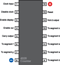
Figure 4-36.
The 4026 decade counter is a CMOS chip that accepts clock pulses on pin 1, maintains a running total from 0 to 9, and outputs this total via pins designed to interface with a seven-segment LED numeric display.
Fundamentals
Counters and seven-segment displays
Most counters accept a stream of pulses and distribute them to a series of pins in sequence. The 4026 decade counter is unusual in that it applies power to its output pins in a pattern that is just right to illuminate the segments of a 7-segment numeric display.
Some counters create positive outputs (they “source” current) while others create negative outputs (they “sink” current). Some seven-segment displays require positive input to light up the numbers. These are known as “common cathode” displays. Others require negative input and are known as “common anode” displays. The 4026 delivers positive outputs and requires a common cathode display.
Check the data sheet for any counter chip to find out how much power it requires, and how much it can deliver. CMOS chips are becoming dated, but they are very useful to hobbyists, because they will tolerate a wide range of supply voltage—from 5 to 15 volts in the case of the 4026. Other types of chips are much more limited.
Most counters can source or sink only a few milliamps of output power. When the 4026 is running on a 9-volt power supply, it can source about 4mA of power from each pin. This is barely enough to drive a seven-segment display.
You can insert a series resistor between each output pin of the counter and each input pin of the numeric display, but a simpler, quicker option is to use just one series resistor for each numeral, between the negative-power pin and ground. The experiment that I’m describing uses this shortcut. Its disadvantage is that digits that require only a couple of segments (such as numeral 1) will appear brighter than those that use many segments (such as numeral 8).
If you want your display to look bright and professional, you really need a transistor to drive each segment of each numeral. An alternative is to use a chip containing multiple “op amps” to amplify the current.
When a decade counter reaches 9 and rolls over to 0, it emits a pulse from its “carry” pin. This can drive another counter that will keep track of tens. The carry pin on that counter can be chained to a third counter that keeps track of hundreds, and so on. In addition to decade counters, there are hexadecimal counters (which count in 16s), octal counters (in 8s), and so on.
Why would you need to count in anything other than tens? Consider that the four numerals on a digital clock each count differently. The rightmost digit rolls over when it reaches 10. The next digit to the left counts in sixes. The first hours digit counts to 10, gives a carry signal, counts to 2, and gives another carry signal. The leftmost hours digit is either blank or 1, when displaying time in 12-hour format. Naturally there are counters specifically designed to do all this.
Counters have control pins such as “clock disable,” which tells the counter to ignore its input pulses and freeze the display, “enable display,” which enables the output from the chip, and “reset,” which resets the count to zero.
The 4026 requires a positive input to activate each control pin. When the pins are grounded, their features are suppressed.
To make the 4026 count and display its running total you must ground the “clock disable” and “reset” pins (to suppress their function) and apply positive voltage to the “enable display” pin (to activate the output). See Figure 4-36 to see these pins identified.
Assuming that you succeed in getting your counter to drive the numeric display, you’re ready to add two more counters, which will control the remaining two numerals. The first counter will count in ones, the second in tens, and the third in hundreds.
In Figure 4-37, I’ve continued to use arrows and numbers to tell you which pins of the counters should be connected to which pins of the numeric display. Otherwise, the schematic would be a confusing tangle of wires crossing each other.
At this point, you can give up in dismay at the number of connections—but really, using a breadboard, it shouldn’t take you more than half an hour to complete this phase of the project. I suggest you give it a try, because there’s