Make: Electronics (51 page)
Authors: Charles Platt

something magical about seeing a display count from 000 through 999 “all by itself,” and I chose this project because it also has a lot of instructional value.
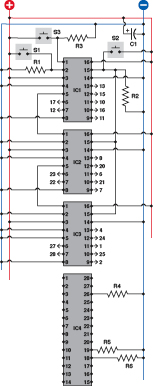
Figure 4-37.
This test circuit, laid out as you would be likely to place it on a breadboard, allows you to trigger a counter manually to verify that the display increments from 000 upward to 999.
Component values:
All resistors are 1K.
S1, S2, S3: SPST tactile switches, normally open
IC1, IC2, IC3: 4026 decade counter chips
IC4: Kingbright 3-digit common-cathode display
C1: 100 µF (minimum) smoothing capacitor
Wire the output pins on IC1, IC2, and IC3 to the pins on IC4, according to the numbers preceded by arrows. The actual wires have been omitted for clarity. Check for the pinouts of IC4.
S1 is attached to the “clock disable” pin of IC1, so that when you hold down this button, it should stop that counter from counting. Because IC1 controls IC2, and IC2 controls IC3, if you freeze IC1, the other two will have to wait for it to resume. Therefore you won’t need to make use of their “clock disable” features.
S2 is connected to the “reset” pins of all three counters, so that when you hold down this button, it should set them all to zero.
S3 sends positive pulses manually to the “clock input” pin of the first counter.
S1, S2, and S3 are all wired in parallel with 1K resistors connected to the negative side of the power supply. The idea is that when the buttons are not being pressed, the “pull-down” resistors keep the pins near ground (zero) voltage. When you press one of the buttons, it connects positive voltage directly to the chip, and easily overwhelms the negative voltage. This way, the pins remain either in a definitely positive or definitely negative state. If you disconnect one of these pull-down resistors you are likely to see the numeric display “flutter” erratically. (The numeric display chip has some unconnected pins, but this won’t cause any problem, because it is a passive chip that is just a collection of LED segments.)
Always connect input pins of a CMOS chip so that they are either positive or negative. See the “No Floating Pins” warning on the next page.
I suggest that you connect all the wires shown in the schematic first. Then cut lengths of 22-gauge wire to join the remaining pins of the sockets from IC1, IC2, and IC3 to IC4.
Switch on the power and press S2. You’ll see three zeros in your numeric display.
Each time you press S3, the count should advance by 1. If you press S2, the count should reset to three zeros. If you hold down S1 while you press S3 repeatedly, the counters should remain frozen, ignoring the pulses from S3.
Fundamentals
Switch bounce
When you hit S3, I think you’ll find that the count sometimes increases by more than 1. This does not mean that there’s something wrong with your circuit or your components; you are just observing a phenomenon known as “switch bounce.”
On a microscopic level, the contacts inside a pushbutton switch do not close smoothly, firmly, and decisively. They vibrate for a few microseconds before settling; the counter chip detects this vibration as a series of pulses, not just one.
Various circuits are available to “debounce” a switch. The simplest option is to put a small capacitor in parallel with the switch, to absorb the fluctuations; but this is less than ideal. I’ll come back to the topic of debouncing later in the book. Switch bounce is not a concern in this circuit, because we’re about to get rid of S3 and substitute a 555 timer that generates nice clean bounceless pulses.
Pulse Generation
A 555 timer is ideal for driving a counter chip. You’ve already seen how to wire a 555 to create a stream of pulses that made noise through a loudspeaker. I’m reproducing the same circuit in Figure 4-38 in simplified form, using the positive and negative supply configuration in the current project. Also I’m showing the connection between pins 2 and 6 in the way that you’re most likely to make it, via a wire that loops over the top of the chip.
For the current experiment, I’m suggesting initial component values that will generate only four pulses per second. Any faster than that, and you won’t be able to verify that your counters are counting properly.
Install IC5 and its associated components on your breadboard immediately above IC1. Don’t leave any gap between the chips. Disconnect S3 and R3 and connect a wire directly between pin 3 (output) of IC5 and pin 1 (clock) of IC1, the topmost counter. Power up again, and you should see the digits advancing rapidly in a smooth, regular fashion. Press S1, and while you hold it, the count should freeze. Release S1 and the count will resume. Press S2 and the counter should reset, even if you are pressing S1 at the same time.
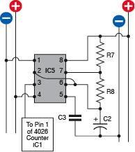
Figure 4-38.
A basic astable circuit to drive the decade counter in the previous schematic. Output is approximately 4 pulses per second.
R7: 1K
R8: 2K2
C2: 68 µF
C3: 0.1 µF
IC5: 555 timer
 No Floating Pins!
A CMOS chip is hypersensitive. Any pin that is not wired either to the supply voltage or to ground is said to be “floating” and may act like an antenna, sensitive to the smallest fluctuations in the world around it.
The 4026 counter chip has a pin labeled “clock disable.” The manufacturer’s data sheet helpfully tells you that if you give this pin a positive voltage, the chip stops counting and freezes its display. As you don’t want to do that, you may just ignore that pin and leave it unconnected, at least while you test the chip. This is a very bad idea!
What the data sheet doesn’t bother to tell you (presumably because “everyone knows” such things) is that if you want the clock to run normally, the clock-disable feature itself has to be disabled, by wiring it to negative (ground) voltage. If you leave the pin floating (and I speak from experience), the chip will behave erratically and uselessly.
All input pins must be either positively or negatively wired, unless otherwise specified.
Refinements
Now it’s time to remember that what we really want this circuit to do is test a person’s reflexes. When the user starts it, we want an initial delay, followed by a signal—probably an LED that comes on. The user responds to the signal by pressing a button as quickly as possible. During the time it takes for the person to respond, the counter will count milliseconds. When the person presses the button, the counter will stop. The display then remains frozen indefinitely, displaying the number of pulses that were counted before the person was able to react.
How to arrange this? I think we need a flip-flop. When the flip-flop gets a signal, it starts the counter running—and keeps it running. When the flip-flop gets another signal (from the user pressing a button), it stops the counter running, and keeps it stopped.
How do we build this flip-flop? Believe it or not, we can use yet another 555 timer, in a new manner known as bistable mode.
Fundamentals
The bistable 555 timer
Figure 4-39 shows the internal layout of a 555 timer, as before, but the external components on the righthand side have been eliminated. Instead, I’m applying a constant negative voltage to pin 6. Can you see the consequences? Suppose you apply a negative pulse to the trigger (pin 2). Normally when you do this and the 555 starts running, it generates a positive output while charging a capacitor attached to pin 6. When the capacitor reaches 2/3 of the full supply voltage, this tells the 555 to ends its positive output, and it flips back to negative.
Well, if there’s no capacitor, there’s nothing to stop the timer. Its positive output will just continue indefinitely. However, pin 4 (the reset) can still override everything, so if you apply negative voltage to pin 4, it flips the output to negative. After that, the output will stay negative indefinitely, as it usually does, until you trigger the timer by dropping the voltage to pin 2 again. This will flip the timer back to generating its positive output.
Here’s a quick summary of the bistable configuration:
- A negative pulse to pin 2 turns the output positive.
- A negative pulse to pin 4 turns the output negative.
- The timer is stable in each of these states. Its run-time has become infinite.
It’s OK to leave pins 5 and 7 of the timer unconnected, because we’re pushing it into extreme states where any random signals from those pins will be ignored.
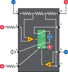
Figure 4-39.
In the bistable configuration, pin 6 of a 555 timer is perpetually negative, so the timer cycle never ends, unless you force it to do so by applying a negative pulse to pin 4 (the reset).
In bistable mode, the 555 has turned into one big flip-flop. To avoid any uncertainty, we keep pins 2 and 4 normally positive via pull-up resistors, but negative pulses on those pins can overwhelm them when we want to flip the 555 into its opposite state. The schematic for running a 555 timer in bistable mode, controlled by two pushbuttons, is shown in Figure 4-40. You can add this above your existing circuit. Because you’re going to attach the output from IC6 to pin 2 of IC1, the topmost counter, you can disconnect S1 and R1 from that pin. See Figure 4-41.
Now, power up the circuit again. You should find that it counts in the same way as before, but when you press S4, it freezes. This is because your bistable 555 timer is sending its positive output to the “clock disable” pin on the counter. The counter is still receiving a stream of pulses from the astable 555 timer, but as long as pin 2 is positive on the counter, the counter simply ignores the pulses.
Now press S5, which flips your bistable 555 back to delivering a negative output, at which point the count resumes.