Make: Electronics (82 page)
Authors: Charles Platt

Theory
Inside a stepper motor (continued)
In reality, the magnets are not separate from each other. The edge of a rotor is magnetized in zones that alternate between south and north polarity. And instead of multiple coils, there are just four windings that go around all the magnetic cores. But the principle is exactly the same. The 3D rendering gives a general idea, and the photograph shows what I found when I cracked open a typical stepper motor.
Now bear in mind that when this device is driven by a set of 555 timers, we don’t just connect negative to one wire at a time on the left, leaving the others floating. In reality, at any given moment, three of the timers have a negative output and the fourth has a positive output. The last diagram in Figure 5-112 shows this situation.
Suppose the top wire is positive while the other three are negative, as shown in Figure 5-113. The positive output does nothing, because it is balanced by the positive power on the other end of the coils. The two negatives attached to the bottom set of coils create equal and opposite forces that cancel each other out (while wasting some power). So the net result is the same as in Step 3.
In fact, you should find that you can disconnect the common wire completely while using the stepper motor with 555 timers, and the motor will still turn, because one of the timers is providing positive power while the others are negative. In fact, you’ll be running them more efficiently this way.
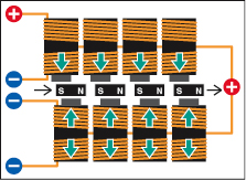
Figure 5-113.
When the motor is driven by four 555 timers, they are activating it by sinking positive voltage from it. The interior workings of the motor look something like this. It’s not the most efficient way to do the job.
Figures 5-114 and 5-115 may help to give you a clearer idea of what the motor actually looks like inside.
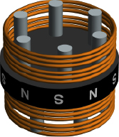
Figure 5-114.
This 3D rendering gives a better idea of what a typical stepper motor looks like inside. The copper coils and gray cylinders are stationary, while the black disc rotates between them.
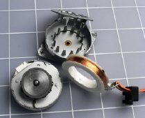
Figure 5-115.
When a stepper motor is broken open, this is what you’re likely to find. On the left, the rotor of the motor, which has a magnetized band around its circumference, is still attached to the lower half of the casing. On the right, the upper half of the casing has been opened, and the coil has been removed (actually the winding you can see consists of two coils, wound in opposite directions). The spikes are the magnetic cores that exert force on the rotor.
Speed Control
If you are a truly exceptionally observant, you may have noticed that I left pin 5 of each of the timers unconnected in the schematic for driving the stepper motor in Figure 5-108. Normally, pin 5 should be grounded through a capacitor to prevent it from picking up stray voltages which can affect the accuracy of the chip.
I left the pins unconnected because I had a plan for them. In fact, changing the timing of the chip is exactly what we want to do now, as a way to change the speed of the stepper motor.
If you tie pin 5 of all four timers together, as shown in Figure 5-116, and put a 2K trimmer potentiometer (shown in Figure 5-117) between them and the negative side of the power supply, you’ll find that as you turn the trimmer to reduce its resistance, the timers start to run faster. Figure 5-118 shows the breadboard layout. Eventually, when the resistance goes below around 150 ohms, everything stops. The LEDs go dark, because you’ve reduced the voltage on pin 5 below the threshold level that the 555 timer finds acceptable.
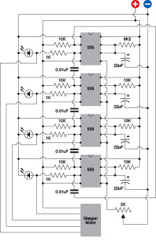
Figure 5-116.
To adjust the speed of the sequence of 555 timers, their control pins (pin 5 on each timer) are linked together and attached to a trimmer potentiometer that adjusts the resistance between the pins and the negative side of the power supply.

Figure 5-117.
Close-up of a trimmer potentiometer with pins spaced at 1/10 inch for insertion in a breadboard or perforated board. The brass screw, at top-left, turns a worm gear inside the unit, allowing precise adjustment of internal resistance.
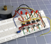
Figure 5-118.
The trimmer potentiometer has been added to the circuit, allowing motor speed control.
Initially I suggested a step time of 1/4 second just so that you could see what was happening. When you’re actually using this circuit, you’ll never need it to run as slowly as that. So you can increase the entire range of speeds. Remove the 22 μF timing capacitors and substitute, say, 4.7 μF capacitors, or smaller. Now when you adjust the potentiometer, you’ll get a useful range of speed.
Adding Autonomy
Currently, the circuit simply does what you tell it to do. The next step is to make it autonomous—in other words, give it the illusion of making up its own mind. I’m thinking that instead of a trimmer potentiometer, we could substitute a photocell, properly known as a photoresistor. Typically, the resistance of a cadmium sulfide photo resistor is highest in the dark, and lowest when light shines on it.
One problem with photoresistors is that they’re not as widely available as many other types of electronic components. If you search Mouser.com, for instance, you’ll find virtually nothing. Partly this is because the online search function at Mouser is the weakest feature of the site, and partly it’s because Mouser is not oriented toward hobbyists. What you need to do is conduct a “product search.” Go to
http://www.google.com/products
, enter the search terms “CdS” and “photocell,” and you’ll find a bunch of cheap cadmium sulfide components from places you may never have heard of.
Because photoresistors seem to come and go as erratically as DC motors, I am not offering any part numbers. You can buy any product that has an appropriate minimum resistance (in bright light) and maximum resistance (in the dark). If you find a component that ranges from 500 to 3,000Ω, that would be a good choice. If the only ones you can find have a higher minimum than 500Ω, you could consider putting a couple of them in parallel.
Setting Up Your Light Seeking Robot
Why would you want to control the speed of a stepper motor by using a photo resistor? Because the original objective was to build a robot that is attracted to light.
The idea is simple enough: use two stepper motors, each controlling the speed of one wheel of the cart. Use two photoresistors, each controlling the speed of the opposite stepper motor. When the righthand photoresistor picks up more light, its resistance lowers, causing the lefthand set of timers to run faster, which will make the lefthand wheel run faster. Thus, the cart will turn toward the light. Figure 5-119 illustrates the concept.
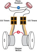
Figure 5-119.
If two photoresistors control the speed of two 555-timer arrays, the difference in speed between one wheel and the other can turn the cart toward a light source.
Before you start wiring more 555 timers, though, you might consider doing the job with a more appropriate component. The ULN2001A and ULN2003A are chips containing Darlington amplifiers specifically designed to deliver current to inductive loads such as solenoids, relays, and (you guessed it) motors. Each chip has seven inputs that require very little current, and seven outputs that can deliver 500mA each. The inputs are TTL and CMOS compatible (the 2001A has a wider tolerance for voltages than the 2003A) and each channel of the chip functions as an inverter, so that when the input goes high, the output goes low and sinks current. This is of course just what we need for our stepper motor that has a common positive connection.