Make: Electronics (85 page)
Authors: Charles Platt

Now for the chip itself. Note that the pins for positive and negative power are
exactly opposite
to those for the 555 timer, so be careful!
Set up your breadboard following the schematic shown in Figure 5-131. Note that I am showing the stereo socket on its underside, because I think that’s how you’ll have to use it with the breadboard. If you try to stick its pins into the holes in the board, they will fit, but when you insert the plug into the socket, the thickness of the plug will tend to raise the socket up so that it loses contact. I really think the way to go is to solder wires to the pins on the socket and push the wires into the breadboard. See Figure 5-133.
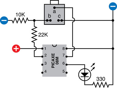
Figure 5-131.
The schematic of a test circuit for the PICAXE 08M shows the underside of the stereo socket, the essential 10K and 22K resistors on the input pin, and an LED to show an output from the chip.
Be aware that the PICAXE manual shows things differently (although I have retained their labeling convention for the parts of the socket and the parts of the plug, identified as a, b, and c).
One little detail about the socket that is commonly supplied for use with the PICAXE: typically it has two
pairs
of contacts for the connections labeled b and c in the manual, and in my diagram. When you solder a connection, your solder joint should include
both
of the contacts in each pair, as shown in Figure 5-132.
Remember that the PICAXE must have 5 volts DC, and remember that your voltage regular will deliver this voltage reliably only if you give it extra voltage on its input side. If you provide it with 9 volts, that will provide a good amount of headroom.
The 22K and 10K resistors are essential for using the chip; see the following warning note for an explanation. My schematic also includes an LED and a 330Ω resistor, but they are needed only for the test that we’ll be making momentarily.
 Pin 2 Pull-Down
Always include the 22K resistor and the 10K resistor in the configuration shown in Figure 5-131. These resistors apply correct voltage to the serial connection, and when you’re using the PICAXE on its own, they pull down the voltage on pin 2.
If pin 2 is left unconnected (floating), it may pick up random voltages, which the chip can misinterpret as a new program or other instructions, with unpredictable and undesirable results.
The 22K and 10K resistors should be regarded as permanent items accompanying your PICAXE regardless of whether you have it attached to your computer.
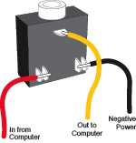
Figure 5-132.
Correct wiring of the socket is essential. When soldering wires to the lower terminals, make sure that you attach the wires to both of the terminals in each pair.
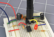
Figure 5-133.
The breadboard version of the test schematic, with the plug of the USB download cable inserted in the socket on the board. The PICAXE chip can now receive a downloaded program, and will immediately start to execute it.
Verifying the Connection
Follow these steps carefully every time you want to program or reprogram your PICAXE chip:
1.
Insert the USB plug of your PICAXE cable into the same USB port that you used before.
2.
Start the Programming Editor (or AXEpad if you are using a Mac OS or Linux).
3.
In the Programming Editor, select View→Options to verify that the editor is using the right COM port and is expecting the 08M PICAXE chip.
4.
Plug the stereo plug on the free end of the USB cable into the stereo socket that is now wired into your breadboard. See Figures 5-133 and 5-134.
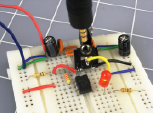
Figure 5-134.
After the program has been downloaded, the plug can be removed, and the program will continue to run, causing the LED to continue flashing.
5.
Check your wiring, and then connect your power supply to the breadboard.
6.
Click the button labeled “program” in the Program Editor window to tell the software to look for the PICAXE.
What If It Doesn’t Work?
The first thing to do is pull out the plug of the USB cable from the PICAXE breadboard, leaving the other end of the cable attached to your computer. Set your multimeter to measure DC volts, and attach its probes to sections b and c of the plug. See Figure 5-135. Now click the “program” button again, and your meter should show 5 volts briefly coming out of your computer to the plug on the end of the cable.
If you detect the voltage, the software is installed and working properly. In that case, there’s a problem on your breadboard, either in the chip or in the wiring around it.
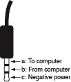
Figure 5-135.
The stereo plug on the end of the USB download cable can be used for fault tracing. A multimeter set to measure DC volts can be attached to sections b and c of the plug to establish whether the Programming Editor is sending data through the serial connection.
If you cannot detect any voltage, the software probably wasn’t installed properly, or is looking for the wrong serial port. Try uninstalling it and reinstalling it.
Your First Program
Finally you’re ready to create your first program. Type the following code into the Programming Editor window:
main:
high 1
pause 1000
low 1
pause 1000
goto main
Be sure to include the colon after the word “main” on the first line. See Figure 5-136 for a screenshot. The indents are created by pressing the Tab key. Their only purpose is to make program listings more legible. The software ignores them.
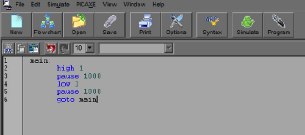
Figure 5-136.
This screenshot shows the first test program as it should be displayed by the Programming Editor (on a Windows computer).
Click the Program button in the Programming Editor to download this program into the chip. As soon as the download is complete, the chip should start flashing the LED, lighting it for 1 second and then switching it off for 1 second. Figure 5-137 shows the steps that you should have followed to program the chip.

Figure 5-137.
Four steps to create and run a program on the PICAXE controller chip.