Make: Electronics (86 page)
Authors: Charles Platt

Now for the interesting part: disconnect the USB cable from the breadboard. The chip should continue flashing.
Disconnect the power supply from the breadboard and wait a minute or two for the capacitors to lose their charge. Reconnect the power, and the chip will start flashing again.
The program that you downloaded to the chip will remain in the memory inside the chip and will begin running every time power is applied to the chip.
Decoding the Code
Let’s take a look at the little program that you typed in. The first line identifies a section of the program. This program only has one section, and we’re calling it “main.” Any word with a colon after it is the name of a section of a program:
main:
The second line tells the chip to send a high output from Logic Pin 1:
high 1
The program doesn’t use the usual pin numbers on the chip. It uses what I will call “logic pin numbers.” Figure 5-138 shows how they are numbered. Figure 5-139 shows their multiple functions. I have put Logic Pin 0 in parentheses because its main purpose is to send data to the computer through the USB cable. It can do double duty as a digital output, but you have to disconnect it from the USB cable first. It’s easy to forget to do this. It’s a hassle that I prefer to avoid.
The third line of the program tells the chip to wait for 1,000 milliseconds. This of course is the same as one second:
pause 1000
The fourth line tells the chip to change Logic Pin 1 back to its low state:
low 1
The fifth line tells the chip to wait for another 1,000 milliseconds:
pause 1000
The last line tells the chip to go back to the beginning of the “main” section:
goto main
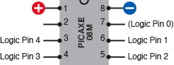
Figure 5-138.
The conventional pin numbers of the PICAXE chip are incompatible with the numbering system that is used in the PICAXE programming language. To minimize confusion, this guide refers to “Logic Pins” when using the numbering system that is required for programming the chip.
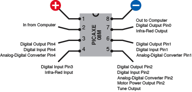
Figure 5-139.
Many of the pins on the PICAXE 08M have multiple functions, which can be selected by appropriate program instructions.
Editing
What if you want to change the program? No problem! Use the Programming Editor to change one of the lines in the program. Substitute 100 instead of 1000 milliseconds, for instance. (The
pause
command can be followed by any number up to 65535.) In your program, don’t use a thousands comma in any of the numbers that you specify.
Plug the USB cable into the breadboard again, hit the Program button on the screen, and the new version of the program will be automatically downloaded to the chip, overwriting the old version.
What if you want to save the program for future use? Just go to the File menu in the Programming Editor and save the program onto your computer’s hard drive. Because the PICAXE uses a variant of the BASIC computer language, it adds a .
bas
filename extension.
Simulation
If you make a simple typing error, the Programming Editor will find it and stop you from downloading your program. It will leave you to figure out how to fix the line that contains the error.
You’ll need to check the second part of the PICAXE documentation, which contains all the programming statements and their correct syntax. At the time of writing, this is stored at
http://www.rev-ed.co.uk/docs/picaxe_manual2.pdf
.
Even if all the statements in your program are correctly typed, it’s a good idea to run a simulation of what they’ll do, before you download them. This is easily done: click the “simulate” button on the menu bar of the Programming Editor. A new window will open, displaying a diagrammatic view of the PICAXE chip and showing you the states of its pins. (Note that if you use very short
pause
commands, the simulation won’t run fast enough to display the time accurately.) A simulation screenshot is shown in Figure 5-140.
The >> button at the bottom-right corner of the simulation window will open up a list of all the variables in your program. So far, it doesn’t have any variables, but it soon will. All the zeros on the righthand side are binary numbers, which you can ignore for now.
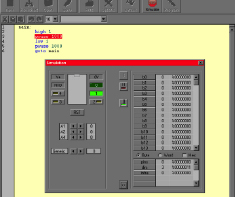
Figure 5-140.
This screenshot shows the simulation window that can be opened in the Program Editor to test program code before it is downloaded to the chip. The values of variables are shown in the section on the right. The pin states are shown on the left.
Loops
Here’s another thing I’d like you to try. Rewrite your program code as shown here and download it onto the PICAXE:
main:
for b0 = 1 to 5
high 1
pause 200
low 1
pause 200
next
wait 2
goto main
Note that
b0
is letter b followed by a zero, not letter b followed by letter O. The extra indents once again are added to make the listing easier to understand. The four lines beginning “high 1” and ending “pause 200” will be executed repeatedly. It’s helpful to see them as a block.
Watch the light and see what happens. It should flash five times quickly, then wait for two seconds, and then repeat. You just added a
loop
to your program. You can use a loop if you want something to happen more than once.
b0 is known as a
variable
. Think of it as being like a little “memory box” with its name, b0, on a label on the outside. Figure 5-141 illustrates this concept. This particular memory box can contain any number from 0 through 255. The loop begins by telling the computer to put number 1 in the box, then process the remaining statements, until the word “next” sends the processor back to the first line, at which point it adds 1 to the contents of b0. If the value of b0 is 5 or less, the loop repeats. If the value is 6, the loop has run five times, so it’s over, and the PICAXE skips down to the “wait 2” statement after “next.” See Figure 5-142 for an annotated version of the program listing.

Figure 5-141.
To understand how a program works, visualize a variable as being like a “memory box” with its name on the outside and a number stored on the inside.
“Wait” is a PICAXE command that is measured in whole seconds, so “wait 2” waits for 2 seconds. Then “goto main” begins the procedure all over again.
If your flashing-light demo worked out as planned, it’s time to take the next step and make the chip do something more useful.
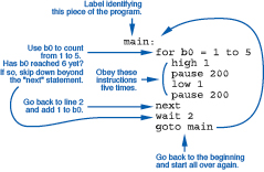
Figure 5-142.
The blue annotations explain what the program, on the right, is telling the PICAXE to do.
Fundamentals
Basic PICAXE parameters
Here are some of the most useful parameters of the PICAXE:
- The PICAXE requires 5 volts DC, regulated.
- The inputs and outputs of the PICAXE are compatible with 5-volt logic chips. You can attach them directly.
- Each PICAXE pin can sink or source up to 20mA. The whole chip can deliver up to 90mA. This means that you can run LEDs directly from the pins, or a piezo noisemaker (which draws very little current), or a transistor.
- You can use a chip such as the ULN2001A Darlington array (mentioned in the previous experiment) to amplify the output from the PICAXE and drive something such as a relay or a motor.
- The chip executes each line of your program in about 0.1 milliseconds.
- The 08M chip has enough flash memory for about 80 lines of program code. Other PICAXE chips have more memory.
- The PICAXE provides 14 variables named b0 through b13. The “b” stands for “byte,” as each variable occupies a single byte. Each can hold a value ranging from 0 through 255.
- No negative or fractional values are allowed in variables.
- You also have 7 double-byte variables, named w0 through w6. The “w” stands for “word.” Each can hold a value ranging from 0 through 65535.
- The “b” variables share the same memory space as the “w” variables. Thus:
- b0 and b1 use the same bytes as w0.
- b2 and b3 use the same bytes as w1.
- b4 and b5 use the same bytes as w2.
- b6 and b7 use the same bytes as w3.
- b8 and b9 use the same bytes as w4.
- b10 and b11 use the same bytes as w5.
- b12 and b13 use the same bytes as w6.
- b14 and b15 use the same bytes as w7.
Therefore, if you use w0 as a variable, do not use b0 or b1. If you use b6 as a variable, do not use w3, and so on.
- Variable values are stored in RAM, and disappear when the power is switched off.
- The program is stored in nonvolatile memory, and remains intact when the power is off.
- The manufacturer’s specification claims that the nonvolatile memory is rewritable up to about 100,000 times.
- If you want to attach a switch or pushbutton to a pin and use it as an input, you should add a 10K pull-down resistor between the pin and the negative side of the power supply to hold the pin in a low state when the switch is open. Figure 5-143 shows how pull-down resistors should be used in conjunction with a SPST switch or a pushbutton.
- On the 08M chip, if you apply a varying resistance between Logic Pins 1, 2, or 4, and the negative side of the power supply, the chip can measure it and “decide” what to do. This is the “Analog-Digital Conversion” feature—which leads to our next experiment.
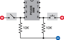
Figure 5-143.
The PICAXE can respond to the state of a switch or button attached to any of its input-capable pins. A 10K resistor must be used to pull down the state of the pin when the contact of the switch or button is open. Otherwise, you may get unpredictable results.