Make: Electronics (81 page)
Authors: Charles Platt

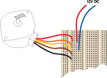
Figure 5-106.
The simplest test of a stepper motor is to apply voltage manually to each of its four control wires, while a piece of duct tape, attached to the output shaft, makes it easy to see how the motor responds.
The data sheet will tell you in what sequence to apply power to the wires. You can figure this out by trial and error if necessary. One thing to bear in mind: a stepper motor is very tolerant. As long as you apply the correct voltage to it, you can’t burn it out.
To see exactly what the motor is doing, stick a piece of duct tape to the end of the shaft. Then apply voltage to wires, one at a time, by moving your negative power connection from one to the next. You should see the shaft turning in little steps.
Inside the motor are coils and magnets, but they function differently from those in a DC motor. You can begin by imagining the configuration as being like the diagram in Figure 5-107. Each time you apply voltage to a different coil, the black quadrant of the shaft turns to face that coil. In reality, of course, the motor turns less than 90° from one coil to the next, but this simplified model is a good way to get a rough idea of what’s happening. For a more precise explanation, see the upcoming section “Theory: Inside a stepper motor.”
Bear in mind that as long as any of the wires of the motor are connected, it is constantly drawing power, even while sitting and doing nothing. Unlike a regular DC motor, a stepper motor is designed to do nothing for much of the time. When you apply voltage to a different wire, it steps to that position and then resumes doing nothing.
The coil inside the motor is holding the shaft in position, and the power that the motor draws will be dissipated as heat. It’s quite normal for the motor to get warm while you’re using it. The trouble is, if you use a battery to power it, and you forget that you have it connected, the battery will not hold its charge for long.
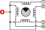
Figure 5-107.
This greatly simplified diagram helps in visualizing the way in which a stepper motor works. In reality, almost all motors rotate by less than 90° in response to each pulse.
Quick Demo
Now that you’ve proved that your motor is functional, how can you actually run it? You need to send a pulse to each of the four wires in turn, in a rapidly repeating sequence. If you can also adjust the speed of the pulses, so much the better. I’m thinking that for a quick and simple demo, you can handle the challenge simply by using four 555 timers, all of them in monostable mode, with each one triggering the next.
The schematic in Figure 5-108 shows what I have in mind. It looks more complex than it really is. Each timer has the same pattern of components around it, so after you create the first module, you just make three copies of it.

Figure 5-108.
A very quick and simple circuit to control a stepper motor uses four 555 timers, each in monostable mode, triggering each other in a repeating sequence.
I’ve used a 10K resistor to pull up the input to each 555, so that the timers are naturally in their quiescent state. A 0.01 μF capacitor links the output from one timer to the input of the next so that they are electrically isolated from each other, and the capacitor just conveys a “spike” of voltage when one timer finishes its “on” cycle, and its output goes low, which triggers the next.
On the righthand side, I’ve used 10K resistors and 22 μF capacitors to generate a cycle of about a quarter of a second—except that the topmost timer has a 8K2 timing resistor. The reason for this is that when power is first applied, the timers will all be waiting for each other to begin, and timers 2 and 4 or 1 and 3 may fire together. By giving one timer a shorter cycle than the others, I minimize this problem.
The LEDs are included just to give you some visual verification of what’s happening. Without them, if you make a wiring error, the motor may turn to and fro erratically, and you won’t know why. Initially you can run your circuit with only the LEDs connected, just to make sure it works. Figure 5-109 shows the breadboarded circuit before the motor is plugged in. Then add the motor by plugging its wires into the breadboard, where you’ll make connection with the outputs (pins 3) of the timers. See Figure 5-110.
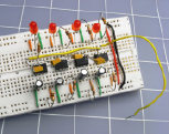
Figure 5-109.
To test the control circuit for errors, four LEDs show the outputs from the four 555 timers. The loose yellow wire at the righthand side connects to pin 2 of the first timer. Touch the free end of this wire to the positive side of the power supply to reset the timers, and then, if necessary, make a brief negative connection with the free end of the wire to restart their sequence.
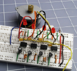
Figure 5-110.
After the circuit has been tested, the motor can be added by hooking its control wires to the outputs of the four 555 timers.
Apply power, and you should see the motor turning in steps, in sequence with the LEDs. If the LED sequence isn’t stable:
1.
Connect a wire directly from the input (pin 2) of the topmost timer to the positive side of the voltage supply, and wait for the timers to calm down.
2.
Restart the sequence by disconnecting the free end of this wire, or (if necessary) touch the free end of it briefly to the negative side of the supply, to trigger the first timer.
One thing you may have noticed, if you’re paying very close attention: the common terminal of the motor is connected to positive. Therefore, when each timer flashes positive, that positive signal isn’t actually powering the motor. The
low
outputs from the three timers that are
not
firing at any given moment are sinking current from the motor. It seems quite happy with this arrangement. You’ll need some theory to understand why.
Theory
Inside a stepper motor
If you check the Wikipedia entry for stepper motors, you may see a very nice 3D rendering showing a toothed rotor and four coils arrayed around it. Maybe stepper motors used to be manufactured like this once upon a time, but not anymore.
Imagine two horizontal rows of coils. In the space between them is a series of little magnets, like a freight train, that can move left or right, as shown in Figures 5-111 and 5-112. Each coil has two windings, in opposite directions, so that current through one winding will create an upward magnetic force while current through the other will create a downward force. Each row of windings is connected in parallel, so that they switch on and off simultaneously.
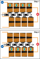
Figure 5-111.
This sequence shows the first two steps as the rotor of a stepper motor (shown as a series of north-south magnets) moves in response to pulses through electromagnets.
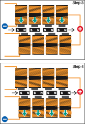
Figure 5-112.
After taking another two steps, the motor will be back where it started at Step 1 in Figure 5-111.
In Step 1, the negative connection energizes the upper windings of the upper coils, which creates an upward magnetic force. I’ve shown this force using blue-green arrows so that you won’t mistake it for a flow of electricity. It so happens that this force attracts the north poles of the magnets and repels the south poles, so if the magnets begin in the position shown in Step 1, they will want to move one step to the right.
This brings them to the position shown in Step 2. Now the upper windings of the lower coils are energized, and again, this produces an upward force, which again attracts the north poles and repels the south poles.
This advances the magnets to their location in Step 3. Now the lower windings of the upper coils are energized, producing a downward force. This repels the north poles of the magnets and attracts their south poles. So the magnets keep moving.
They reach the position shown in Step 4. The lower windings of the lower coils are energized, producing a downward force which continues to attract the south poles while repelling the north poles. So the magnets move a final step to the right—which leaves them in the same orientation shown in Step 1. And the process can repeat all over again.