X and the City: Modeling Aspects of Urban Life (64 page)
Read X and the City: Modeling Aspects of Urban Life Online
Authors: John A. Adam

which is
constant
, so the apparent acceleration of shadow length must find its explanations in the realm of psychology and perception, not physics and mathematics . . .
Exercise:
It is more frequently the case that the base of the lamp is some fixed distance
y
from me when I walk right past it. (I try to make sure that
y
≠ 0.) Generalize the above argument to show that

where
θ
(
t
) is the angle the shadow makes with my direction of travel. Clearly this result approaches that of (21.3) as
x
increases.
Question:
Will the shadow of my head move parallel to me as I walk?
=
α
: DOUBLE IMAGES FROM PLATE GLASS DOORS AND WINDOWS
This is a nice little “inverse problem.” Sometimes we may see a double image of the moon or a distant lamp from a window as we walk along a road at night.

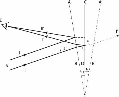
Figure 21.3. Geometry for multiple reflections in (slightly) nonparallel window surfaces for angle of incidence
i
(relative to the back surface
CD
). The (highly exaggerated) angle between the front and back surfaces is
α
radians.
Although this can occur if the window has plane parallel surfaces, it is a very tiny effect unless the surfaces are in fact not parallel. Suppose that the front and back faces of the window (
AB
and
CD
respectively in
Figure 21.3
) are inclined at a very small angle
α
, so the angle between the reflected rays
I
′ and
II
′ will be 2
α
. This is seen by calculating the deviation of a single reflected ray when the “mirror” is rotated through an angle
α
; using the fact that the angle of reflection is equal to the angle of incidence, it is 2
α
. In the (greatly exaggerated)
Figure 21.3
, a pair of parallel rays,
I
and
II
, from an assumed distant source are shown impinging on the back and front surfaces of the plate glass, respectively. If we imagine the back surface
CD
to be a mirror (which in effect it is), it will give a reflected image of the surface
AB
along
A
′
B
′, and an image of the ray
I
′ along
I
″. Then the ray
II
″ has effectively passed through a narrow prism with apex angle 2
α
, and the minimum angular deflection in the ray path caused by such a prism is 2(
n
− 1)
α
, which when added to the 2
α
above gives a total contribution of 2
nα
,
n
≈ 1.5 being the refractive index of the glass. Thus if we can estimate the angular distance (3
α
) between the two reflections, the angle between the surfaces is one third of that amount.
Exercise:
The
minimum
angular deflection
D
in the symmetric path of a ray through a triangular prism of apex angle
γ
can be shown to be

where
n
is the refractive index of the prism. Show that for the plate glass window this reduces to
D
= 2(
n
−1)
α
as stated, if
α
is small.
How large might the angle
α
be and how might we estimate it? Nowadays plate glass windows are made to a very high degree of precision, but in older houses there can be some small but significant angles between the surfaces. There are probably other distortions in the thickness of the glass, but these will be ignored here.
Suppose we are close enough to estimate the lateral distance
d
between the images on the glass, and that the distance between the eye and the window is
L
. From
Figure 21.4
, representing the approximate geometrical relationship between
L, d
, and the rays
I
′,
II
″, we see that
p
≈
d
cos
i
≈
L
tan 3
α
≈ 3
αL
, so that the angle between the faces is

Suppose that
L
= 10 m, and
d
= 1 cm = 10
−2
m for an angle of incidence
i ≈
30°. We now see that
α
≈ 3 × 10
−4
radians (or about one minute of arc). Over a distance of 30 cm (about a foot) then, and on the basis of these figures, the thickness of the glass changes by about 30 sin
α
≈ 30
α
≈ 10
−2
cm or 0.1 mm, a tiny amount, to be sure! So, if the glass surfaces are very nearly parallel (as here), it follows that the angle
α
is extremely tiny indeed, and the angular distance between the two reflections is three times “extremely tiny,” that is, still very tiny! So the double images that can be observed from large distances are almost inevitably produced by nonparallel glass surfaces. If we and the light source are both close enough to parallel glass surfaces, however, then the images may then be quite well separated if the light is not at normal incidence to the window.

Figure 21.4. Detail for equation (21.5).

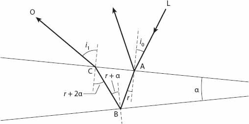
Figure 21.5. Generic ray paths for a wedge of angle
α
.
Let’s pursue this a little farther. From
Figure 21.5
we see that the ray
LABCO
exits the upper glass surface at an angle
i
1
to the normal direction, where sin
i
1
=
n
sin (
r
+ 2
α
). Also, sin
i
0
=
n
sin
r
. Using the fact that
α
is a very small angle, we may write that sin
i
1
≈
n
sin
r
+ 2
nα
cos
r
. The difference between the angles
i
0
and
i
1
is small, so we can use differential notation to write
sin
i
1
− sin
i
0
≈
δ
(sin
i
) ≈ 2
αn
cos
r
.
Therefore

Note that
k
(0) = 2
n
. That is, for normal incidence, the angular separation of the images is approximately 2
nα
= 3
α
for
n
= 1.5 (a generic value for the refractive index of glass). This is the result obtained earlier in this section. A graph of the function
k
(
i
) is shown in
Figure 21.5
. Clearly, this indicates that
Δi
, the approximate angular separation of the images, becomes larger and larger the closer the ray’s angle of incidence is to the plane of the surface.