125 Physics Projects for the Evil Genius (61 page)
Read 125 Physics Projects for the Evil Genius Online
Authors: Jerry Silver

Figure 103-1
Circuit for studying capacitors
.
Discharging4. Record the current in mA every five seconds (this is easier with partners). If you miss a reading, keep going and catch the next five-second interval. Keep going until the current becomes too small to read. If other capacitor/resistor combinations are used, a different time interval than five seconds may be more appropriate.
- When the charging part is complete, open all the switches.
- Close SW1 and leave SW2 open.
- Close SW3 and start the timer.
- As before, record the current in five-second intervals.
With SW2 closed, the capacitor will charge. LED2 will light, but slowly fades as the voltage builds and the current flow decreases. For the 10 kΩ resistor and the 1000 μF capacitor given in the parts list, the charging will be about two-thirds complete in 50 seconds, as shown in
Figure 103-2
.
With SW3 closed, the capacitor will discharge as indicated in
Figure 103-3
. After 50 seconds the voltage will have dropped from 10 volts to around 3.7 volts. LED3 will light and will slowly fade as the capacitor discharges.
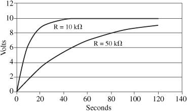
Figure 103-2
Capacitor voltage versus time for a 1000 μF capacitor charging through 10 kΩ and 50 kΩ resistors
.
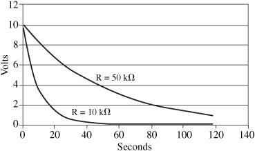
Figure 103-3
Capacitor voltage versus time for a 1000 μF capacitor discharging through 10 kΩ and 50 kΩ resistors
.
In general, the time to charge or discharge two-thirds of capacity is characterized by the time constant. For a capacitor
C
(in Farads) and a resistor
R
(in ohms), the time constant, τ (in seconds), is given by τ = RC. The
time constant
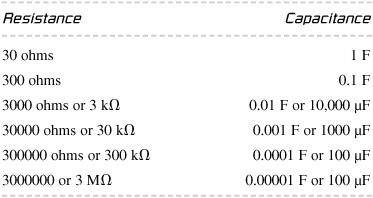
represents the time where the current during charging or the voltage during discharging has decreased by about two-thirds. The following combinations of resistor and capacitor (
Table 103-1
) give a reasonable time constant of 30 seconds, which gives measurable results in this experiment.
Table 103-1
The current for a charging capacitor is given by
I
= I
o
e
−t/RC
The voltage for a charging capacitor is given by
V
= V
o
(1 – e
−t/RC
)
The current for a discharging capacitor is given by
I
= I
o
e
−t/RC
The voltage for a discharging capacitor is given by V = V
o
e
−t/RC
When t = the time constant, RC, then e
−t/RC
= e
−1
= 0.37. This mean a discharging capacitor has dropped to about one-third of its original value or has discharged about two-thirds.
If you have other resistors and capacitors available, try (small) increases or decreases in values, and then determine how it affects the time to charge and discharge. The previous
Table 103-1
gives combinations that result in reasonable time constants and serves as a good starting point. Adjust your measurement interval as needed.
Use a current and voltage sensor that displays these parameters as a function of time on a computer. A combination voltage/current sensor (part number PS-2115) is available from PASCO that displays both parameters simultaneously in DataStudio software.
Make a graph of voltage (or current) versus time for your discharge data with voltage on a linear scale and time on a logarithmic scale. Use an exponential curve fit to an Excel scatter plot to find the argument of the exponent. Compare that with –1/RC.
A capacitor is a device that stores electrical energy. The rate of charging and discharging depends on the size of the capacitor and the resistor it is charging or discharging through. The bigger the capacitor and the resistor, the longer these processes take. The charging and discharging is an exponential function of time that approaches a saturation value.
Is the magnetic force more powerful than gravity
?
In this experiment, you use a magnetic field to defy gravity and hold a magnetic object suspended in the air. You also explore the effectiveness of various materials in shielding the effects of the magnetic field.
- powerful permanent magnet
- ring stand with clamp
- paper clip
- 12 inches of (low mass) string
- materials to test as a shield: glass, paper, copper
- piece of tape
1. Secure the magnet to the ring stand, so the most powerful magnetic field is directed downward.
2. Tie the string to the paper clip.
3. Bring the paper clip near the overhead magnet. It should be close enough for the magnetic field to exert a force on the clip, as shown in
Figure 104-1
.
4. Tape the other end of the string to the table. Using tape enables you to easily make slight adjustments in the string length.
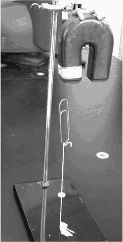
Figure 104-1
Photo by S. Grabowski
.
5. At this point, if you are going to show this to someone, this would be a good point to have them come into the room.
6. Observe what happens when you bring the paper clip closer, and then further from the magnet.
Expected Results7. Try blocking the magnetic field by using any of the following potential shielding materials: glass, paper, copper, iron.
The paper clip appears to defy gravity and will be held suspended above the table. Depending on the strength of the magnet, a gap of a few millimeters can be established between the paper clip and the magnet.
The magnetic field can be shown to penetrate through materials, such as glass, paper, wood, or copper. See
Figures 104-2
and
104-3
.
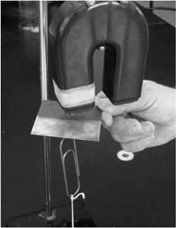
Figure 104-2
Does a magnetic field pass through a conductor? This should leave little doubt. Photo by S. Grabowski
.
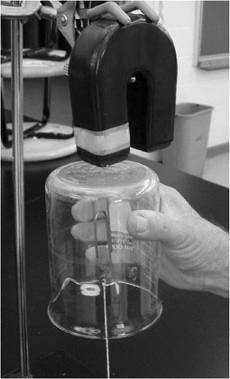
Figure 104-3
Does a magnetic field pass through an insulator? Photo by S. Grabowski
.
The force exerted by the magnet is greater than the force of gravity.
Use a very sensitive spring scale or a force gauge to measure the magnetic force exerted on the paper clip.
Magnetic fields exert a force on magnetic objects. This force decreases with distance. The magnetic field penetrates both electrical insulators and conductors.
Magnetic levitation using induction. Electromagnetic ring tosser
.
This is a fun demo with somewhat surprising results. You will use a powerful magnetic field to exert a force on a material that is not normally magnetic. You will generate a circulating current using electromagnetic induction. The result is that the magnetic repulsion causes a metal object to be forcefully thrown into the air.
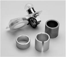
- ring launcher apparatus (Elihu Thomson apparatus). Pictured in
Figure 105-1
is PASCO EM-8661. - copper collar
- aluminum ring
- split aluminum ring
- copper ring