Make: Electronics (88 page)
Authors: Charles Platt

Experiment 36: The Lock, Revisited
The combination lock that I described in
Experiment 20
is especially appropriate for a microcontroller, because it requires a series of operations that resemble a computer program. I’m going to show how this project can be redesigned using a PICAXE 08M, and then leave it to you to consider how some of the other projects in this book could be converted.
You will need:
- The same type of keypad and relay recommended in
Experiment 20
. - A transistor or Darlington array to amplify the output from the PICAXE so that it can drive the relay.
Getting the User Input
Any of the input pins on the PICAXE can sense a switch closing. The trouble is that we only have three pins capable of doing this, and even the most advanced PICAXE chip has fewer than 10 such pins. So how can we attach a 10-key keypad to the 08M?
I have a suggestion: attach various resistors to the keypad, so that each key applies a different voltage to one of the ADC pins. Then use the ADC feature to convert the voltage to a number, and use a table of possible numbers to figure out which key is being pressed. This may not be the most elegant solution, but it works!
The keypad can be wired as shown in Figure 5-147. The asterisk key is still being used to supply power, as in the original experiment, while the pound key resets the relay at the end of your computing session, as before.
Current flows through a series of resistors, beginning with one that has a value of 500Ω. Because this is not a standard value, you will either have to make it by combining other resistors in series, or by presetting a trimmer potentiometer. After that, each button is separated from the next button by a 100Ω resistor. Finally, at the end of the chain, a 600Ω resistor separates the last button from the negative side of the power supply. Again, this is not a standard value, and you may have to use a trimmer.
Add up all the resistances and you have 2K, which is the range that the PICAXE wants us to use. When you press a button, you tap into the chain of resistances. Button 9 puts 600Ω between the PICAXE ADC pin and ground. Button 6 is 700Ω, button 3 is 800Ω, and so on. (You may prefer to lay out the buttons so that the resistance progresses in a more logical fashion. That’s up to you. I chose to lay them out in the way that would be easiest to visualize on a keypad.)
Now look back at the ADC values that I supplied in the table on
page 308
. These are the values that you should get when you press various keypad buttons—but you cannot count on them being absolutely precise, because they may vary if your resistor values are not quite accurate, or if your power supply isn’t exactly 5 volts. It’s not safe to say, for example, that the PICAXE will deliver an ADC conversion value of precisely 77 when the resistance is 600Ω. It’s safer to say that the value will be between 71 and 83. If we specify a range as shown in the following table, we have a much better chance of interpreting each button correctly.
Button number | Range | |
9 | 600 | 71–83 |
6 | 700 | 84–96 |
3 | 800 | 97–108 |
0 | 900 | 109–121 |
8 | 1000 | 122–134 |
5 | 1100 | 135–147 |
2 | 1200 | 148–160 |
7 | 1300 | 161–172 |
4 | 1400 | 173–185 |
1 | 1500 | 191–198 |
Suppose you attach the common pin of your keypad to ADC Logic Pin 2 of the PICAXE. You can now use the Program Editor to write a program that looks like this:
getkey:
readadc 2,b0
let b1 = 3
if b0 < 115 then finish
readadc 2,b0
let b1 = 6
if b0 < 127 then finish
readadc 2,b0
let b1 = 9
if b0 < 138 then finish
readadc 2,b0
let b1 = 2
if b0 < 149 then finish
readadc 2,b0
let b1 = 5
if b0 < 159 then finish
readadc 2,b0
let b1 = 8
if b0 < 169 then finish
readadc 2,b0
let b1 = 0
if b0 < 179 then finish
readadc 2,b0
let b1 = 1
if b0 < 188 then finish
readadc 2,b0
let b1 = 4
if b0 < 197 then finish
readadc 2,b0
let b1 = 7
if b0 < 210 then finish
goto getkey
finish:
readadc 2,b0
if b0 < 250 then finish
return
What does the word “return” mean at the end? I’ll get to that in a second. I want to explain the rest of the routine first.
b0 receives the value supplied by the analog-digital converter when it looks at the keypad. After storing the number in b0, the routine has to figure out which keypad key it matches. The key identity (0 through 9) will be stored in another variable, b1.
The program starts by assigning value 9 to b1. Then it checks to see whether b0 < 84. This means “if b0 is less than 84.” If it is, then the routine tells the PICAXE to “finish,” which means “jump to the finish: label.” But if b0 is
not
less than 84, by default the PICAXE continues on to the next line, which makes a second attempt at guessing which key has been pressed. It assigns number 6 to b1. Now there’s another if-then test—and so on. This process of reassigning values to b1 stops only when it gets to the point where b0 is greater than a number in the table.
If you’re familiar with other dialects of BASIC, this may seem a bit laborious to you. You may wonder why we can’t use a statement such as this:
if b0 > 70 and b0 < 84 then b1 = 9
The answer is that PICAXE BASIC isn’t sufficiently sophisticated to allow this. An if-then statement has to result in a jump to another section of the program. That’s the only permitted outcome.
If you don’t have any prior programming experience, the routine may still seem laborious to you, and perhaps a bit puzzling, too. This is understandable, because you’re getting a crash course in software design without any formal preparation. Still, the PICAXE Programming Editor can be a big help, because it has its simulation feature. Before you can use this, though, you have to precede the routine that I just supplied with a control routine that you must type above it. The screenshot in Figure 5-148 shows you how it should look.
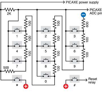
Figure 5-147.
A quick and simple way of attaching a keypad to provide numeric input to the PICAXE uses a chain of resistors totalling 2,000Ω. When a button is pressed, it connects the ADC input pin to a point in the chain. The resistance detected by the input pin can then be converted by the program in the chip to determine which key has been pressed.
I have chosen an arbitrary combination of 7-4-1 for our combination lock. Using these numbers, the main section of the program looks like this:
main:
low 1
gosub getkey
if b1<>7 then main
gosub getkey
if b1<>4 then main
gosub getkey
if b1<>1 then main
high 1
end
I should explain that the <> pair of symbols mean “is not equal to.” So the fourth line of the program means, “if b1 is not equal to 7.”
The value of b1 is supposed to be 7 if the user is putting in the correct combination. So if it’s not 7, the user has entered the wrong value, and the if-then statement sends the PICAXE back to the beginning. In fact anytime the user inputs a number that is not in the correct 7-4-1 sequence, the program sends the PICAXE back to the beginning. This is the way the pure-hardware version of this experiment was set up.
But what is this word “gosub”? It means “go to a subroutine.” A subroutine is any sequence of program statements that ends with the instruction to “return.” So “gosub getkey” tells the PICAXE to mark its current place in the program while it skips to the
getkey:
section of code, which it obeys, until it finds the word “return,” which returns it to the place from where it came.
The PICAXE continues in this fashion until it reaches the word “end.” I had to insert the word “end” because otherwise the PICAXE will continue executing the program and will fall into the subroutine. “End” stops it from doing so. Figure 5-148 shows a screenshot of the complete listing.
So—is that all? Yes, that’s it. If you enter the code into the Programming Editor exactly as I have supplied it, you should be able to run it in simulation mode, and in the simulation window, click the right-arrow beside Logical Pin A2 to increase its value in steps. Each time you pass one of the values in the
getkey:
subroutine, you should see the value for variable b1 change in the display.
This is really all you need to perform the functions of the combination lock. When the PICAXE runs this program, it waits for the correct combination. If it receives the combination, it sends the output from logical pin 1 high; otherwise, logical pin 1 stays low.
The only additional item you need is a transistor or CMOS gate between logical pin 1 and the relay that unlocks the computer, because the PICAXE cannot deliver enough current to operate the relay by itself.
Putting this procedure into a controller chip not only simplifies the circuit, but offers another advantage: you can change the combination simply by rewriting the program and downloading the new version into the chip.
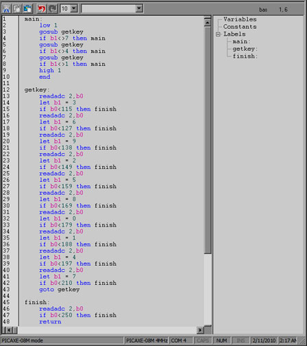
Figure 5-148.
This screenshot shows the complete listing of a program to read a sequence of three keypresses in conjunction with a combination lock. If the sequence is correct, the PICAXE sends a high output from one of its pins. If the sequence is incorrect, the program loops back to the beginning.
Fundamentals
Limitations of MCUs
The PICAXE does have some disadvantages. Its voltage requirements alone restrict you from using it with the kind of freedom of a 555 timer.
Also, although I can get an instant result by plugging a 555 timer into a breadboard and adding a couple of resistors and a couple of capacitors, the PICAXE requires me to add a download socket, hook it up to my computer, write a program in the Programming Editor, and download the program.
Some people don’t like writing software, or they have difficulty thinking in the relentlessly left-brain way that computer programming requires. They may prefer the hands-on process of assembling hardware.
Other people may have the opposite preference. This of course is a matter of taste, but one thing we know beyond all doubt is that computer programs often contain errors that may not reveal themselves until weeks or months later.
The PICAXE, for instance, doesn’t protect you if a number is assigned to a variable that exceeds the limit for that type of variable. Suppose b1=200 and b2=60 and your program tells the PICAXE:
let b3 = b1 + b2
The result should be 260, but byte-size variables can only count up to 255. What happens? You will find that b3 acquires a value of 4, without any warning or explanation. This is known as an “overflow error,” which can be very difficult to predict, because it happens at runtime, when external factors are in control. The code looks perfectly good; the Programming Editor doesn’t find any syntax errors; the simulation behaves properly. But in the real world, days or even months later, an unexpected set of circumstances results in an input that causes the overflow, and because the code is residing inside the chip at this point, you may have a hard time figuring out what on earth went wrong.
Software has its problems. Hardware has its advantages.