125 Physics Projects for the Evil Genius (45 page)
Read 125 Physics Projects for the Evil Genius Online
Authors: Jerry Silver

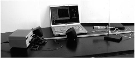
Figure 77-2
Components to measure the speed of sound
.
- Measure the distance between the two speakers when the sound is at maximum level. This distance is one full wavelength, λ, of the sound wave. If you measure this in meters, your calculation for the speed of sound will be in meters per second. (You can get additional data points by measuring different locations, finding the one-half wavelength from the positions when the sound is at a minimum, and then repeating this at various frequencies.)
- Once we have the wavelength, λ, and the frequency,
f
, you can multiply them together to get the velocity using the wave equation:
Expected Resultsv = λf
As before, the speed of sound at 20 degrees centigrade is 343 meters per second.
The speed of sound (in meters per second) as a function of temperature (in degrees centigrade) is v = 331 +0.6T.
Using a 440 Hz tone, the distance separating the microphones to get a 343 meter per second value for the speed of sound is 0.78 meters (78 centimeters).
A 1000 Hz tone would require a 0.343 meter separation to result in the expected value for the speed of sound.
Two waves traveling in the same direction add together to form a new wave. If the crests of the two waves rise at the same time and place, the waves are said to be in phase and reinforce each other to produce a louder sound. This is called constructive interference. This occurs when the two sources of the sound are separated by exactly one full wavelength. (One wave gets a one-wavelength head start, but both are in phase at the detector.) If we know the wavelength and the frequency of the sound, we can easily determine its velocity according to the relationship v = λf.
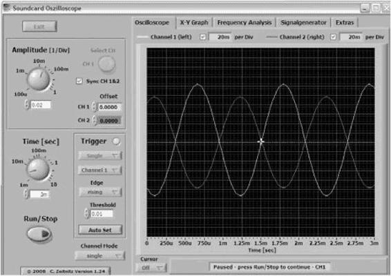
Figure 77-3
Sound waves (amplitude versus time) shifted by one-half a wavelength as a result of traveling through the distance between the two speakers
.
Destructive interference occurs when one wave crests while the trough of a second wave is passing. This happens when the source of the two waves is separated by half a wavelength.
If you can set up two microphones to your oscilloscope, there is another way to do this that shows the process of interference more clearly. In this case, you follow basically the same procedure as the previous one, except you have one speaker and two microphones. You move the microphones until you observe destructive interference. This occurs when the crest of one wave is at the same place as the trough of the other wave, as shown in
Figure 77-3
. This method does not work using a sound intensity meter or by listening carefully, as did the previous method.
Following this method, you can use the capability that many oscilloscopes have to detect the point at which the waves are separated by one-half a wavelength. This involves plotting one signal versus the other on the display. When this
x
versus
y
plot is a straight line with a slope equal to a negative one, as shown in
Figure 77-4
, your signals are 180 degrees out of phase and separated by one-half wavelength.
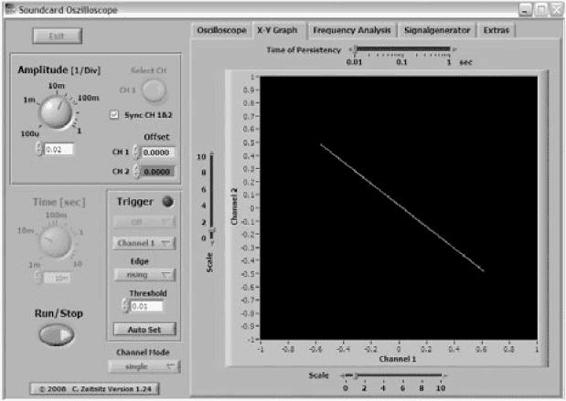
Figure 77-4
x–y plot of two sound waves showing the separation of one-half wavelength
.
Another configuration that can be used to find positions of a constructive and destructive interference is shown in
Figure 77-5
. This method is analogous to the double slit technique used by Thomas Young with light and is explored in
Project 83
. The wavelength is given by:
λ = dsinθ
where
d
is the separation between the speakers and θ is the angle between the midpoint between the speakers and the point where constructive interference is identified.
Using a similar principle, the speed of light can also be measured in the lab. An apparatus is commercially available that determines the wavelength of a known frequency of light by measuring the distance between positions of constructive interference. The measurement is much trickier than the one in this experiment because the speed of light is so much greater than the speed of sound. The same basic approach, however, can be applied to either sound or light.
The speed of sound can be determined if the wavelength and frequency of the wave are known. The wavelength for a given frequency can be determined by finding the distance at which constructive interference occurs.
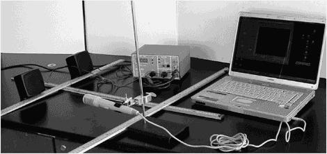
Figure 77-5
Finding the locations of maximum and minimum sound intensity to determine the speed of sound
.
Light
Ray optics. Tracing the path of light using a laser
.
This is a perfect way to see for yourself how light moves when it encounters mirrors and lenses.
- laser pointer
- set of lenses, including convex, concave, rectangular, and semicircular lens; rectangular prism and 60 and right-angle prisms (90°, 45°, 45°) and (90°, 30°, and 60°)
- 2 small flat mirrors
- sheet of paper (plain or gridded)
- ruler
- protractor
- dark room
- Caution—You should use a low-power laser pointer and be careful
not
to shine the laser where it could hit anyone’s eyes. Remember, you are working with optical devices that change the path of the light, so be careful to avoid stray light rays that could affect anyone’s eyes. - Place your object lens (or mirror) on a flat table.
- Place a sheet of paper underneath the lens.
- Trace the outline of the lens on your paper. Leave enough room to draw incoming and outgoing lines.
- Darken the room.
- Shine the laser at a slight angle, so its straight line path can be seen on the paper.
- For each of the lenses, put three or more dots along the path to define the incident path.
- Observe its path through the lens (or reflected from the mirrors). You may need to slightly adjust the angle (to the plane of the table) to make the transmitted ray visible. Depending on your lenses, you may not be able to see the laser light going through the lens. Also, be careful not to mistake light that may sneak underneath the lens as a ray that follows the intended optical path through the lens. Also (again depending on your lenses), you may need a slightly different angle to make the
incident laser line visible as you would need for the refracted line. If this is the case, make sure you come into the lens along the same incident line that you drew. - Make three or more dots to define the refracted (or reflected) paths.
- Make a dot where the light enters the lens and where it leaves the lens.
- Connect the dots with straight lines showing the incident (incoming) line, the straight line through the lens (which is the refracted line), and the transmitted or reflected lines.
- Explore as many of the following optical objects as you have available. The following lists several specific things to focus on.
(Note: All this can be done, if you prefer, on a magnetic chalkboard using lenses with magnetic backs. You can either glue strong magnets to your lens or simply hold the lens to the chalkboard. Make sure that the magnetic chalkboard is strong enough to hold the lens securely and that the magnet does not block the path of the light. Laser levels may be useful because they have built-in angles to make the line visible along a surface. However, they may be a little trickier to focus all the way through the lens.)
Draw a perpendicular line to the surface of the mirror. Shine the laser at the point where the perpendicular line meets the mirror. Place dots along the incident line and the reflected line, and then connect the dots. Compare the incident angle with the reflected angle. Try this for several sets of angles (
Figure 78-1
).
Shine the laser on one of the mirrors and trace its path (by placing dots along the path and connecting them). The path should hit the second mirror, and then reflect off the second mirror. Try this for several angles of incidence on the first mirror. (If you like geometry, set the mirrors at an acute angle. Then, predict and test the angle of the outgoing ray for a given angle of incidence.)
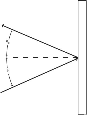
Figure 78-1
Reflection from a plane mirror
.
A
convex lens
is the one that is thicker at the middle than at the ends. Draw a centerline perpendicular to the axis of the lens. Trace the following paths: a) a straight line along the center line through the center of the lens, b) a line above the centerline running parallel to the centerline, c) a line below the centerline running parallel to it. Trace all the lines. Notice where the three lines cross. Measure that distance and put a dot on the centerline on the incident side of the lens that same distance from the lens. Direct the laser at any angle through that dot and trace its path through the lens. Try this for several angles.